tz89
-
Posts
452 -
Joined
-
Last visited
Content Type
Profiles
Forums
Gallery
Events
Store
Everything posted by tz89
-
I'm hoping it becomes a community project. There are lots of ideas and skills on this forum. Best $12 ever!
-
Yes this will work on a 4 cylinder bike (even 6 once I get beyond the conflicting LCD display). A tach should be doable without too much trouble. All you need is an induction coil and some software to translate that into RPM. You could just wrap some wire around a clothespin and clip it to the plug wire on #1. I'll add this to my list of future mods. To do a tach with just the vacuum pulse data coming in is a non-trivial math problem of trying to detect the period of the pulse with very noisy data. Sounds challenging at least. If only my algebra teacher had said it would be useful for motorcycles I might have paid attention. Any Fast Fourier Transformation experts out there? I wonder if there is a simple way given that we know it's a 4 cycle engine with RPM between ~ 500 and 5000.
-
Yes I used it today and it worked quite well. I've never used a carb tune just the oil in the tube method. Very easy. Each cylinder shows a value. You just adjust the sync until you are satisfied. And since all 4 cylinders show at once and there is no oil lag I was done in a few minutes. I'm hoping for good improvement suggestions and I'll revise as I go. It's probably cheaper just to buy a carb tune, but what's the fun in that?!?!
-
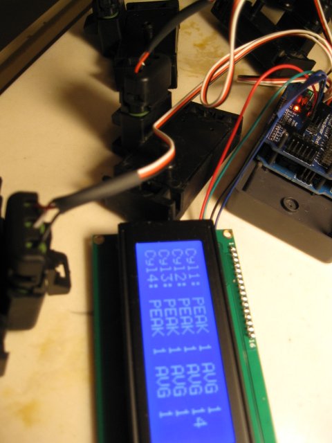
/* Here's the code. Just copy everything and paste into the Arduino IDE. */ /* Modified Smoothing (below) by Tom Hogue 2012 for CarbSync Tool Accepts 0-5v from GM 1 bar MAP sensors Creates arrays of values for all cylinders v01r01 is the basic development version v01r02 adds LCD display v01r03 adds input calibration at startup Future mods smartphone display bluetooth connectivity tach live smooth and sensitivity adjustments Smoothing Reads repeatedly from an analog input, calculating a running average and printing it to the computer. Keeps ten readings in an array and continually averages them. The circuit: * Analog sensor (potentiometer will do) attached to analog input 0 Created 22 April 2007 By David A. Mellis modified 9 Apr 2012 by Tom Igoe http://www.arduino.cc/en/Tutorial/Smoothing This example code is in the public domain. */ #include #include LiquidCrystal_I2C lcd(0x27,20,4); //set the LCD address to 0x27 for a 20 chars and 4 line display /* Define the number of samples to keep track of. The higher the number, the more the readings will be smoothed, but the slower the output will respond to the input. Using a constant rather than a normal variable lets use this value to determine the size of the readings array. Uno board drives the LCD with A4 and A5, leaving only A0-3 for 4 MAP sensors */ const int numReadingsMax = 100; // this should be maybe 5-150. 190+ overflows lcd const int numCylinders = 4; // max is 4 . Reducing to actual will improve processing only slightly int readings[numCylinders][numReadingsMax]; // the readings from the analog input int numReadings = numReadingsMax; // allow this to change to vary smooth vs speed int index = 0; // the index of the current reading int sensitivity = 200; // how fine input is parsed usually 20-100. 1023 max. int thisCylinder = 0; // the index of the cylinder loops int total[numCylinders]; // the running total int average[numCylinders]; // the running average int runPeak [numCylinders]; // running peak value int inputPin[numCylinders]; // the input pin array int pinOffset = 0; // setting to 0 maps cylinders 1-4 to pins 0-3 int calibrate [numCylinders]; // an adjustment for input voltage variance int calibrateCylinder = 0; // int calibrationMean = 0; // the input adjustment added to each reading int calibrationFlag = 1; // use the first readings to calibrate String outString = " "; // int dispCylinder = 0; // void setup() { // initialize serial communication with computer: // Serial.begin(9600); // initialize LCD lcd.init(); lcd.backlight(); // initialize all the readings to 0: for (thisCylinder = 0; thisCylinder { inputPin[thisCylinder] = thisCylinder + pinOffset; // set cylinder pin plus an offset total[thisCylinder] = 0; average[thisCylinder] = 0; runPeak[thisCylinder] = 0; calibrate[thisCylinder] = 0; for (int thisReading = 0; thisReading { readings [thisCylinder][thisReading] = 0; } } } void loop() { // while the serial stream is not open, do nothing: need for leonardo board // while (!Serial) ; using UNO board and LCD not serial output /* for each reading read all cylinders then increment */ for (thisCylinder = 0; thisCylinder { // subtract the last reading: total[thisCylinder] = total[thisCylinder] - readings[thisCylinder][index]; /* read from the sensor. As vacuum increases MAP sensor output signal voltage drops so use map command to reverse output so that more vacuum == lower voltage == higher data points */ readings[thisCylinder][index] = map(analogRead(inputPin[thisCylinder]), 0, 1023, sensitivity, 0) + calibrate[thisCylinder]; // add the reading to the total: total[thisCylinder] = total[thisCylinder] + readings[thisCylinder] [index]; // calculate the average: average[thisCylinder] = total[thisCylinder] / (index + 1); // calculate the peak - look for more efficient method depending on output method runPeak[thisCylinder] = 0; for (int thisPeak = 0; thisPeak { runPeak[thisCylinder] = max(runPeak[thisCylinder], readings[thisCylinder][thisPeak]); } } // advance to the next reading position in the array: index = index + 1; // if we're at the end of the array... if (index >= numReadings) { index = 0; // ...wrap around to the beginning display(); } /* set a short delay between readings to add stability set to approx 1 ?? when running live */ delay (1); } void display(){ if (calibrationFlag == 1) { calibrationFlag = 0; calibrationMean = 0; for (calibrateCylinder = 0; calibrateCylinder {calibrationMean = calibrationMean + average[calibrateCylinder]; } calibrationMean = calibrationMean / numCylinders; for (calibrateCylinder = 0; calibrateCylinder {calibrate [calibrateCylinder] = calibrationMean - average [calibrateCylinder]; } // display the results and pause lcd.clear(); delay(5); for (calibrateCylinder = 0; calibrateCylinder { outString = "Calibrate C"; outString += calibrateCylinder + 1; outString += " Val "; outString += calibrate[calibrateCylinder]; lcd.setCursor(0, calibrateCylinder); lcd.print (outString); delay(5); } delay(3000); } else { /* send results to the lcd */ lcd.clear(); delay(5); for (dispCylinder = 0; dispCylinder { outString = "C"; outString += dispCylinder + 1; outString += ": PEAK "; outString += runPeak[dispCylinder]; lcd.setCursor(0, dispCylinder); lcd.print (outString); delay(5); outString = " AVG "; int chop = average[dispCylinder]; outString += chop; lcd.setCursor(12, dispCylinder); lcd.print (outString); delay(5); } } /* commented out this code for a test // reset all the readings to 0: for (dispCylinder = 0; dispCylinder { total[dispCylinder] = 0; average[dispCylinder] = 0; runPeak[dispCylinder] = 0; for (int dispReading = 0; dispReading { readings [dispCylinder][dispReading] = 0; } } commented out */ }
-
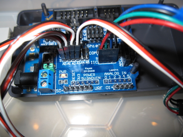
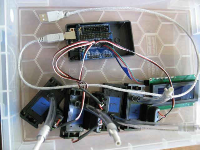
Built a digital sync and you can, too! After reading this forum about installing an aftermarket TCI and in other places about easy to use microprocessing platforms, it occurred to me that one might be able to use multiple MAP sensors to set the carb sync on a bike. I'm no expert on either motorcycles or electronics, so it had to be easy if I was going to do it. And it was easy. The hardest thing for me was figuring out what certain connectors are called and then finding a reasonable source. Point your search engine at “arduino” or go directly to this link: www.arduino.cc to get an idea for the microprocessing end of this. I used the Arduino Uno R3. You can use any, but you'll have to modify my program or write your own. In particular, if you use the kind of LCD display connection I did (IIC) it interferes with two of the ports on the board. On the Uno it's analog 4 and 5, leaving a nice grouping of 0-3 for my 4 sensors to connect. My end goal is to remove the LCD and use a wireless smartphone as the display. When I get that working then this thing could do a 6 carb bike. Goldwing heaven! (On the Leonardo board it's digital 2 and 3.) Here's the parts list. I'll edit this post to improve accuracy as I can. The hard parts (for me): MAP sensors. I found 6 old GM 1 bar MAP sensors for $40 on Ebay and was quite happy. 6 3-tower GM weather-pack housings with male connectors. Spendy with rip-off shipping. You don't really need the plastic housing. You can just solder wires to loose male connectors, and maybe use some heat shrink to tidy up. Save big $$. The rest: Arduino Uno R3. $23. Arduino IDE software (free download). Sensor shield (optional - makes connections easier). $10. LCD IIC display 4x20. $7. 4 count 3-wire board connectors with one end removed and soldered to the weather-packs. $5. 1 count 4-wire board connector to attach the LCD with the +/- polarity rewired. $2. 2 feet 1/4” hose. Cut into 6” lengths and attached to the MAPs. 10 feet 3/16” hose. 4 count ¼ to 3/16 connectors. $5. 4 count caps for the 3/16 hose. $3. The Arduino IDE includes sample programs. I modified one that keeps a running average for input smoothing to load arrays of readings for each cylinder and calculate the peak and average readings. I'm an old software guy but never something like this and never in C. But those old skills came in handy and I wasn't shy about this part. The Arduino doesn't report overflow errors at compile or run time, so I had to do a little digging to debug odd results. For example, if I set the readings array to more than 180, the LCD stopped working. What I figured out was that the sensitivity scale of the readings multiplied by the number of readings had to be less than the max integer value (32k) or it would overflow. If the array got too big the RAM would overflow. I could change to long integers or floating point math I suppose. I could change to a chip or board with more memory because there is a memory size limitation. My rainy weather project will be to go back through and clean up the code. Basically, I just hacked my way forward and didn't worry about the elegance of the code like I did when I was working in software. I didn't know how the compiler or board really worked so why worry about style. The key thing I did was code a self-calibration step. The first time through loading the reading array (with the bike not running), it takes an average of the average of all the MAPS and uses that to establish a calibration adjustment to be applied to all subsequent readings. This way all the MAP sensor circuits are normed to a constant value. It could be normed to zero, but then negative numbers would be more common. To test this live, I hooked up all 4 MAP sensors in turn to the same cylinder on a running bike to see if it would return a consistent value. It did. The nice thing is that build precision is less of a factor which is great for me. It just works with what you have for MAP sensors, wire harness and soldering skills. Assembly is just plugging the shield into the top of the Uno, then plugging in the LCD and the 4 MAP sensors. For power I plugged in a cigarette adapter into my battery maintainer plug, plugged a USB converter into that, and ran a USB cable to the Uno. There are other ways but I had all this handy. The software was already loaded; you just plug the USB into the computer running the IDE and upload. At power up it does the calibration and when you hit the reset button. Nothing to lose by trying. I hooked up 4 hoses to the bike and capped them. Then I tested #1 against all 4 sensors. It read the same, about 159 peak. Then I hooked all 4 up. The bike was in good sync, which I knew because it runs good. But I tweaked all 3 sync adjustments to get them the same. Everything ended up peaking at 158-159. Then I capped the hoses and tested #3 against all 4 sensors. All the same. After that I took it for a ride. Seemed smoother but it was running great already. The numbers don't really mean anything. They depend on how 'sensitive' the software is set. The MAP sensors run at 5v and drop the signal voltage from that as vacuum increases. The UNO board reads an analog voltage and returns a range of integer values. The rest is software. One nice thing - you can crack the throttle without worries. In fact, since you can compare manifold pressure at higher RPMs you may get some diagnostic value if you've got pin holes in a diaphragm or a sticky slide. Hopefully, some engine experts will weigh in on that notion or with better ideas. Things to consider. If you can't find cheap MAP sensors, don't bother. They should all be the same or similar, but the calibration step allows for variances. Try to get the weather-pack connectors included because you'll go broke if you have to buy a small quantity at full retail. If anyone has a better source please let me know. Late 80's GM cars in a junkyard may be a good place to start. There are also less expensive vacuum sensors available for non-automotive applications that are not as rugged. Everything you need can be bought online if you know what to call it. The board connector names still elude me. I just bought stuff until I had something that worked. I'll post the code in a subsequent post. I will be glad for suggestions. I will be especially interested in a) how to build a cool enclosure and b) thoughts about better analysis techniques. I would never post it anywhere else, because the purists would flame you. But this forum is different. Best $12 ever! Lots of pix. If there's a better way to post them I don't know it. Tom

-
Just for fun I'm building a digital sync tool out of old GM MAP sensors. I'll post with pics when it's done. I'm trying to get it to display wirelessly on a smart phone, but if not I'll just use an lcd screen. Stay tuned! Tom
-
It's a mystery, then. Thanks!
-
I didn't think so either. But our IT guys have been scraping off my computer all morning. Something to do with Flash and Java. Apparently "alarms" started going off at IT HQ. They removed and reinstalled Flash and Java, ran a malware scan, removed 1 item. This afternoon I'll find out if they have to wipe the drive completely and start over from bare metal. The original posted link didn't work. Someone posted another link in a subsequent reply. When I clicked that, I got a whole bunch of attempts to install something, that wouldn't let me get control back. I had to turn off the machine, and apparently something still got through.
-
This link put a serious piece of malware on my computer. Admins please delete this thread.
-
It is easy to get it up on the center stand once you know how. It is easy to learn but until you do it seems impossible. Or at least I thought so. Here's how I do it now. With the bike on its side stand and wheel straight ahead, I push down the center stand with my right foot until it touches the ground. I have my left hand on the handle bar and my right hand on the rear seat hand grip. Then I straighten the bike up until the other leg of the center stand touches the ground. It is easy to tell. The next part is easy to do but hard to explain. I push down with my foot on the center stand to use leverage to raise the bike. I tug on the hand grip, not to lift the bike but to help me push against the center stand. The bike is designed to make this easy on level ground.
-

Carbureation Proplems
tz89 replied to DickL's topic in Venture and Venture Royale Tech Talk ('83 - '93)
One more thing. Count the turns on your mix screws and let us know. I suppose it could be as simple as that... but I wouldn't bet on it. There's a thread on here for that. Basically you have to remove the mix screw plugs if they are still in, gently screw in the mix screws to lightly bottom while counting the revolutions. The mix screws are normally set to 2-1/2 turns from bottom. If you are under 2 on any or all you might have found your problem. You will want to re-sync the carbs if you change the mix. -
Carbureation Proplems
tz89 replied to DickL's topic in Venture and Venture Royale Tech Talk ('83 - '93)
It's running too lean. My mechanic was able to clear my carbs without pulling the rack off. There's a tread here for attempting that. My brother did it successfully on his. It's worth a try but if it doesn't work you probably are looking at pulling the rack and doing a proper cleaning. If you are able just to it right first. What worked for my brother was to take off the airbox, diaphragms and spray in a carb cleaner. He used seafoam spray with the long tube but I guess anything that won't eat the diaphragms will do. He counted the turns on the mix screw, then pulled them and sprayed in there. Don't lose the o-rings (I think he swallowed one of his - don't ask...anyway it had to be replaced). He did the exhaust heat test to make sure all 4 were firing, and then ran heavy on the seafoam for a while. That's basically what my mechanic did on my #3 which was missing at idle. Both bikes run great although his needs a sync. -
I use Aerospace Protectant 303 on a microfiber rag and rub it in. Seat looks like new, and is not slippery.
-
Fouled plug, where to start?
tz89 replied to VentureBob's topic in Venture and Venture Royale Tech Talk ('83 - '93)
Have the protective caps over the mix screws been removed? That would suggest that the PO was in there adjusting. If so, you might count the turns in and report back. Maybe #2 is set too rich. -
oily spray from speedo connection??
tz89 replied to tz89's topic in Venture and Venture Royale Tech Talk ('83 - '93)
Just went out to check. The drain screw doesn't seem the culprit. I checked the bottom of the fork - nope. And yet it is coming from somewhere. I checked up the cable to see if it was coming from above and only pooling at the bottom. The cable is dry except for the bottom 8 inches or so. hmmmm... I'm really reaching now - could something come down the inside of the cable? I haven't done any work like lube the cable. But I'm not ready to blame gremlins yet. -
oily spray from speedo connection??
tz89 replied to tz89's topic in Venture and Venture Royale Tech Talk ('83 - '93)
It's a mystery for sure. Seals look okay - no tell-tale oil ring above. No fade on the brakes but this was my initial fear. When I wipe it off it comes off black, black, black. After a few days it's back. Nothing else near it (above it) shows any. It's like a light coating not a lot of quantity. Is there something nearby that could be dripping fork oil? I am really reaching - could something come down inside the cable? I haven't done any work like lube it or anything. Not ready to blame gremlins yet. -
I'm getting a little oily on the bottom of my speedo cable. What could be leaking from that? Any particular fix suggested? Here's a pic. http://db.tt/LkvwHh7f
-
Yes, I've been using flannel lined Carhardts this winter (tho not for rain). I'm looking at the Aerostitch products now, and may buy when I'm in MN next month. Definitely not going cheap then!!
-
How well are you set up to do a little work on your own? Time, tools and work space? Would you be able to pull the valve cover and investigate the valves? What does the oil look like?
-
Computer Levelling System - E4 ??
tz89 replied to ziegler99's topic in Royal Star Venture Tech Talk ('99 - '13)
I re-soldered the pins on the board, and no more E4. Easy to do and there's a thread on this site with pictures. All these boards are old, just swapping may not solve it. http://www.venturerider.org/forum/showthread.php?t=493 -
I'll be interested in a pair of shorter studs with the bullet ends.
-
Every so often the oil warning (bottom left) symbol comes on. It stays on for a while, then goes off. Sometimes it does it a couple of times in a row, then goes off. No particular pattern. There is plenty of oil in the sight window. I do know how to check it. Oil can be new or old. Driving fast or slow. Short haul or long haul. Level or hill. Once it goes off I may not see it again for weeks. The rest of my computer is working. I have two theories based on the best source - near total ignorance. Some kind of electrical connection issue working up on me, or an actual issue with the sensor/sendor. My understanding is this isn't an oil pressure sensor, but something else. What else I don't know. It works like my toilet bowl for all I know. Any clues or suggestions you can send my way much appreciated. Thanks Tom
-
You guys carry a spare of this $100 part? 41R-83350-71-00 FLASHER RELAY ASY Has there been lots of stranded experiences?
-
I got 44mpg without seafoam during a section of a long ride mostly in 5th at 3500rpm. I rode down the coast and back home on the twisties this weekend... about 600 miles altogether. Here's a couple of pix http://db.tt/kvq0ares http://db.tt/xApTtn5g
-
If a bike sits, how long before the float bowls evaporate leaving residue behind? This is just a theoretical question my brother and I debated. What do you think? How long before the well runs dry?