


PGunn
-
Posts
327 -
Joined
-
Last visited
Content Type
Profiles
Forums
Gallery
Events
Store
Everything posted by PGunn
-
I thought that is what they were but figured I better ask. I also looked at the boots off a V-Max and eliminated them right away because of the way they are made. I'm looking in a few places one is in China that makes aftermarket adapters. I need to get the bolt spread and the port opening dimensions of the head and the distance from the face of the flange back to the centerline of the bend to see if they either have or what it will cost to make them. Another limiting factor will be how many have to be ordered but I'll worry about that once I get the info I need to see if they have anything close to what is needed and machining them to get what is needed is an option still. It looks like they start with an aluminum casting they then machine it including an O ring gasket and then they attach a coupler to it for attaching the throttle body. In this case the only problem would be I think is the coupler not being for a throttle body and the internal shape being wrong but one workaround would be to use the ones that are for the throttle bodies being used. Or just order them without a coupler and use the OEM one.
-
Pegscraper The boots in the pictures what size are those and what did they come off of?
-
Pegscraper Thanks for the mounting info. I see what you did and understand why now from what your saying and Squeeze has also said is stay away from the stock OEM boots because of the mismatch in size and look for something that will be the correct fit for the diameter of the bodies I am using… Ok so it’s back to see what I can find in a boot that has the correct upturned angle, or close to it, and that could be modified if necessary to be mounted to an aftermarket flange. I also did some more research on that stuff and it dissolves in gasoline!!! I will not be using it but I did find something that looks more like what would be needed called Seal-All and from what I saw you can use this stuff in / on your gas tank if necessary. http://www.totalmotorcycle.com/reviews/SealAllGlueReview.htm Thanks Guys.....
-
Squeeze You have been a huge help and I really do appreciate everything you have done so far. Thanks for the info on the injectors I have to slow done and check stuff before running off looking at other avenues for solutions. Now still more questions. With using the 35mm bodies I would have liked to use the OEM boots but with the spacing difference being 6.625mm per boot I am already getting the feeling that I will not be able to use the OEM boots no matter how much pushing, stretching, pulling I try to do. What I have thought of is just removing the material off the intake mounting face on the boot but that would never work the flange would either be too thin or totally gone. Now a possible idea would be get another set of boots cut the flange and excess material off and purchase an aluminum flange and the re-mount the boot to the new flange there by making up the difference by removing material from the boot until the boot is in the correct location. This would also give all the adjustment I would need to get the bodies into location for linkage mounting and what not. Just to clear it up a bit remove the material from where the original flange was attached to the boot so if I was to measure from the bolt face side of the intake boot flange back 6.625mm and remove this amount this “should” give me the clearance I will need by allowing each boot to move outward giving me the spread between the bores that I will need. I could then just use a clamp to reattach the boot to an aftermarket flange along with something like this to help seal it: http://cgi.ebay.com/ebaymotors/Motorcycle-Intake-Manifold-Repair-E6000-Black_W0QQcmdZViewItemQQcategoryZ35597QQihZ015QQitemZ250214543382QQrdZ1QQsspagenameZWDVW I am already looking at a set of aftermarket boots that I can hack up for testing. Let me know what you think or if there is an easier / better way to go.
-
One of these might also have what you’re looking for. This one just send the guy an email asking for a login and he will send one to you, it might take a day or two but he usually does send one. I have as far as I can tell I have not been spammed from sending the email to the guy. It is free to sign up and download , well it was the last time I used it. http://www.motorosok.hu/szervizkonyvek/index_eng.htm This one is a search it has quite a few and all are free to download http://pdftown.com/ As a side note if you can setup multiple email accounts with your provider set one up just for stuff like this and let the spam hammer it. I have one that after around 6 months or so the name gets changed because of all the spam that hits it. Also use Internet Explorer to check the mail on the account it keeps the bad stuff on the site and off your machine.
-
Squeeze Thanks for the info I finally did find the pickup leads and it would have been nice if Yamaha had labeled it something other then pickup. Throttle body mounting Left to right I received the VFR 800 bodies today they are out of a 2004. I found the side to side should not be a huge deal but I have said that before. I separated them as far as side to side goes and the linkage connecting them can be either modified or remanufactured and the connecting tube for the fuel rails can be shortened if I need to or just make a new one to the correct length. The side brackets mount onto bosses which makes the location a positive location with no movement once they are bolted into place. I will more then likely have to remake the side plates to hold the bodies in position and with the offset I can incorporate the bend into the mounting plates to make up for this. Front to back Now from the distances that Pegscraper gave me earlier the distance on the front to back mounting is 80mm and I just did a quick measurement of the throttle bodies and it is close but by no means dead on comes out at approximately 95.25mm and splitting the difference means that the location for each body is off by around 6.625mm. This means the bodies are going to be closer to the heads by this amount also. My question here is what would be the easiest way to correct / make up this distance and would it interfere with the heads by contact? Just as a why I am asking all these questions is it is 13 degrees F outside and that makes working any of this out on my bike almost impossible. Boots I have 1 of the VFR boots and when you say I will need to use them because of an out of round connection. I don’t see the outside diameter of the body where the boot mounts being out of round and the inside looks the same as other throttle bodies. Can you give me more information on this? Also how would you use them or would I have to make some mounts that bolt to the heads? Injectors I just compared the difference between the Honda VFR 800 injectors and the Yamaha R1 injectors and the Yamaha injectors have a longer reach (?) then the Honda ones. So it looks like I’ll have to find an injector that has the same output specifications as the R1 injector but are dimensionally the same as the Honda injector.
-
Pegscraper I have looked for the crank sensor and can't find it in the service manual I have a copy that is all pictures in a PDF format and can't be searched can you give me some direction on its location (page) or what are the color codes on the wires so I can chase it down in the wiring diagram? I did find the throttle bodies from a Honda VFR 800 should work they have a 35 mm bore and come in a somewhat squared pattern and with a little feathering of the stock boots should work but I will know more once they get here. Once again thanks for the help.
-
Squeeze Ok this is getting a lot clearer now that I have someone to work with who knows what problems there are. So what I need to do is dump the R6 bodies keeping the injectors and find a set with the inside bores closer to the stock carb size which makes total sense now that I understand what you mean by the turbulence inside the boots with the difference between the bore sizes and what I thought would work and what I need to make it work. And yes space is at a premium here under the tank and I am hoping to use the stock intake but I have also thought about making up 2 air boxes out of aluminum and using them but that’s down the road. With the injector sizing that part I did see that info on the Megasquirt site and did some quick figuring which was another reason for going to the R1 as it came the closest with out going overboard on the injector size. So now it’s back to matching up a throttle body to the boot size. I just wish I had asked these questions before I got started it would have save some time. Once again thanks for the info and clearing the waters a little bit more…. Msegelle The benefits are I can tune the system with my laptop setting up the fuel flow according to what I will be doing long trips or just putting around. It will also increase gas mileage and power (HP) of the bike. Some have seen increases of 10 - 15 hp and around a 15% (5) increase in mpg on similar size bikes and with gas now at 3.00+ a gallon I’ll take the 15% and it will pay for itself over time. I am trying to keep the total cost under $1,000 using parts from other bikes and right now the biggest cost is the ECU at $400.00.
-
You guys might be interested in this from Google. It’s free GPS through your phone and it works pretty well from what I'm hearing from the guys (Sales) at work. Check these links.... http://www.google.com/mobile/gmm/mylocation/index.html http://www.google.com/mobile/gmm/index.html#utm_source=en-et-maps&utm_medium=et&utm_campaign=en Basically: If you don't have GPS on your phone it uses the cell towers to locate you on the map within an area you can then pinpoint to your location and have it give you directions from that point to where you want to go. If you have GPS on your device it will use it to locate you then direct you. This is not for all phones but take a look at it and see if it's useable. I hate the fact that phone providers charge for every little thing when the service is free without their device. In this case it's their device and it's still free....
-
Jimbob5 Thanks I will look into these ….. Squeeze The R1 throttle bodies are off a 2006 but I see some issues with them already. 1) Dual throttle plates and the top set are motor driven. The motor driven set can be removed and once the shaft is removed and those holes can be plugged. A lot of unnecessary work so I am more then likely going to look into another set. 2) Fuel pump I am going aftermarket to get the needed pressure along with a pressure regulator if one is not included with the throttle body set. For the fuel return I am going to pull the tank and have one added on where the tank vent is located but on the other side with a slightly longer tube into the tank. Thanks for the info…. Pegscraper Ok to answer the why question first… No real answer here other then I want to see if it can be done, how hard is it to do and could a swap from parts already out there be done. I also would like to see what the difference on a dyno will be and like you I hate getting into the theory stuff also. It’s like the Hypercharges I just put on, why because I wanted to. Now to the other questions… 1) Ok the intake boot distances are what I was looking for and I should have been clearer on that, I am looking at trying to keep the stock boots for now. I’ll have pull mine down to get in there and see how it is setup and go from there. I was not looking at machining out adapters but it is not out of the question. I have a small machining center in my basement and with 15 years in the aerospace industry as a machinist I have a good idea as to what is going to be involved, a true labor of love…J. I will also have to look into other boots from other bikes, why build if you can buy? 2) The crank sensor is the best to use thanks for the info on that and it is still an odd fire engine so the Microsquirt is the best ECU in this application from what I have read in a dollar for dollar comparison. The Microsquirt is made by the same people who make the Megasquirt but comes preassembles and is weather tight. Thanks for the info also…. Ok now from what I am seeing from both Squeeze and Pegscraper is this is not going to be as easy as I first thought and is going to require some more thinking on my part but I still have not given up yet. Now for a couple of more questions: It looks like you both are in agreement on the intake boots not working because of their design. Is this because of the bend in the boot? I would like to try and get the throttle bodies to mount like the carbs do or is this way off base? Making a linkage setup was my first thought when I looked into this and I already have a few ideas but I want to get the bodies mounted before I travel that road. I am going to do this step by step and build / modify as I go so I am not looking at getting this done anytime real soon. I don’t want to miss any riding time because I’m in the middle of something and can’t get the bike out and my wife is dead set against buying a second bike….. Now for the throttle bodies themselves will the ones I have as far as the inside diameter of the bore goes work (CFM air flow)? I have no set reason to use these other then I thought they would work. But after getting them I am seeing drawbacks to them, the dual throttle plates and that the bodies are made in pairs. I am getting the feeling the set driven by the motor (top set) would have to be pulled and the shaft holes plugged. No big deal but is it worth the effort when another set of throttle bodies without these features would give more adjustment as far as fitment goes be the better way to go?
-
I am looking at converting my 06 to fuel injection and I have a few questions some of you might be able to help with. The first thing is carb spacing on the Venture. Now if anyone has removed their carbs from the bike (second gen) or has a spaer set sitting around and if you could post or send me the spacing outside to outside and inside to inside, (center to center) on the side to side and front to back measurements that would be a big help. I want to see which FI throttle body setup comes the closest to that spacing so mounting will involve the least amount of custom work on spacing. Second is how are the coils triggered to fired and is the firing order still odd fire. is there a trigger wheel or sensor somewhere i can't find. Here is what I am planning on doing and I am open to any help / suggestions given. So far I have purchased a set of R1 throttle bodies ($120.00). These are from a bike putting out 135 hp at 13,000 (?) rpm and I think the fuel and air flow should be more then enough for a 1300 cc, 98 hp, 5,000 rpm engine and the wiring harness ($50.00). The throttle body I bought came with all the sensors still in place along with the injectors and wiring. The only sensors I need to add is the air flow sensor and a water temp sensor. I’m looking at installing the air flow sensor it in the tee fitting right before the air boxes that sit on top of the current carbs. The water temp I am going to purchase a second water temp housing and see if there is enough room to drill and tap it for a second temp sending unit. I am going to go with the Microsquirt ECU ($400.00) to handle fuel delivery only for now but it will handle a ton of other features also. So far the only issue I’m running into is the throttle bodies, I may have to go with a set off another manufacture so I can adjust the spacing correctly as the ones I bought have a fixed spacing between each pair. Now I am going to be working on this when the weather isn’t so good and the bike could be down for a few days at a time. As I work along I’ll keep you guys posted on progress and problems. Also if anyone can foresee and issues that are already know please let me know as I really don’t want to invest a bunch of cash on a project that isn’t going to work. Thanks....
-
Thanks, it only took around an hour per side to make them and K&N makes replacement filters for them. All the work on them was done using a saws all and a belt sander. It really was pretty stright forward the only testing was making sure the correct spacer was installed. The butterflys will work but your right they for the most part hidden and not having the ram air setup makes using the vacume setup usless anyways. Without the vacume connections they stay open all the time and act as a passive intake anyways.
-
I have completed the install and attached some pictures of it completed. I also attached a zip file with the install instructions in Word format and and in Adobe PDF format.
-
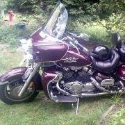
I have looked all over and could not find any articles on mounting these on a Venture, I have an '06. I picked up a pair on EBay which are real left and right hand Hyperchargers from a Harley with a CV carb mount. I have mocked up the right side and the mounting is a lot easier then it looks. I'm waiting for some parts to come in so I can have the right side finished mounted before I start the left side. Now I am mounting these for looks alone and I have no intensions of setting these up to work as ram air intakes because I do not want to cut holes in the lower fairings and route the duct to them. The mount I have working so far is by using the original Yamaha intake mount and by cutting it down to basically a flat surface. After getting it to fit reasonably flat to the Hypercharger I drilled the mounting holes through it using the Hypercharger hole pattern as the pattern. Next I glued a piece of 1/4 inch rubber to the mount this helps cover the rough surface and will allow the 5/8 spacer (5/8" CV bolt pattern Spacer: J&P Cycles) something to seal against. You need around 1 inch spacing between the Yamaha mount and the Hypercharger to get the right side to mount without any interference. I have been looking over the right hand Hypercharger and I noticed that even if you bought 2 right side units (standard with the CV Mount) one of them can be converted to a left using a hot glue gun to mount the screen to the opposite side of the case. This is how they did it and the mounting hole locations are of no difference because of the way I'm mounting them. You need to buy the CV Mount Hyperchargers because they have 3 mounting holes and the back surface is flat and the bolt pattern is in a circumference around the hole. Once I have them completed I'll upload an updated install with pictures. Now as a side note I worked on least a 1/2 dozen different ways to mount these right down to machining my own adapters and mounts out of aluminum. After planning everything figuring prices and not counting my own time I found that buying the Yamaha intake mounts (SKU: 4XY-14431-02-00 $13.00 +/- each) and cutting them to fit (they are a rubber / plastic material) was a lot cheaper and easier, You can cut it with a hacksaw and then belt sand it flat. The CV spacers come in 3 different sizes 1/4, 5/8, and 7/8 from J&P Cycles. The 1/4 inch thick rubber I had but I did lookup on EBay and there is some 1/8 inch thick on the site and with the 7/8 thick spacer it should work just as well. Attached is the picture of the model of the Hypercharger I am using. I also have tried to lookup the left side unit (600178 number on the side of the box) and can't find it anywhere.
-
I haven't used them at night yet but the ones I bought came with a 5 deg spread which would make them more of a spot light. They do have wider angled ones on the site up to 60 deg I think but I don't think I would go over 30 deg. Just looking at them in the day light the light it self looks whiter then the stock one.
-
Yes they most certinally do. I received mine yesterday and they installed with out an issue. I wanted to wait until I had installed them before I posted here and I do have the stock Yamaha passing lights also.
-
A week or so ago one of my driving lights went and I started looking around locally for a replacement. Talk about sticker shock.. NAPA 25.00 plus tax . So I checked here and saw the JP Cycles link and checked them, 18.00 plus shipping that came to more but getting a halogen over a standard one would think was a fair deal. But I was still thinking that was still too much for a 4.5" bulb and I spent around 45 minutes searching the internet. Well I found 1 site after another where the prices were 15.00+ each plus shipping. I did finally find 1 site that makes the others look like true over priced specialty lights, they are not specialty lights. I was also surprised at the average life of these lights: Standard = 300 hours Halogen = 2,000 hours Halogen Xenon = 5,000 hours Now this site http://www.1000bulbs.com/search.php?search_data=par36&cat=&x=73&y=5 has the prices almost anyone can afford (6.85 - 7.98) and with wattage rattings from 2.5 to 150 and 6 - 28 volts. I purchased the Halogen Xenon lights 35 watt lights. Now one draw back to this site is you have to spend 20.00 not including shipping. Well I was switching types and would need 2 for the bike and figured ok 1 for a spare to meet the 20.00 purchace requirement for a total price 35.73 including shipping not bad I thought. I then noticed a price reduction if you order 4 or more so I added a 4th and the priced went to 36.62. I ordered 4 and received them 5 days later and now have a lifetime supply for around 10.00 or less over the total cost of 1 from most other sites.
-
Modulite Trailer Isolation Relay
PGunn replied to Freebird's topic in Computer, Lights, Horns, Other Electrical
I have a question on this solenoid thing and what I'm planning on doing (this for each side). 1) put the oem turn signal across the solenoid side pins 85 and ground to pin 86 2) put the oem parking lights power lead to pin 30 3) from pin 87A to the parking light 4) from pin 87 to the turn light Now the way I figure it when not using the turn signal the parking lights in the rear are on. When I activate the turn signal the parking light on that side goes out but the turn lights light up. You should be able to do the because the parking light has it's own connector and the main oem can be split between the two sides. I am also putting the solenoids behind the the license plate and running all but the oem wiring into one of those behind the license plate document safes with a terminal strip. This way I can easily connect my HD tail lights, my extra led parking / break lights and the trailer connections. If I am wrong about using the parking lead to power the turn lights let me know. -
Free Shop Manual for the 06 Venture
PGunn replied to PGunn's topic in Royal Star and Royal Star Tour Deluxe Tech Talk
Well there has been 53 hits on this and even if 1/2 of them download it is going to be real slow -
http://labs.trunkful.com/LIT-11616-12-60.pdf I would hurry on this or if you can pass it around. Once the word gets out you can bet it will be pulled. It's a 53 meg file and also is not the fastest download out there. Also if you need the owners manual it is http://labs.trunkful.com/LIT-11626-16-15_18.pdf