-
Posts
3,621 -
Joined
-
Last visited
Content Type
Profiles
Forums
Gallery
Events
Store
Everything posted by Prairiehammer
-

Fork Overhaul
Prairiehammer replied to dna9656's topic in Venture and Venture Royale Tech Talk ('83 - '93)
OK, I am not correct in telling you the damping rod will come out the bottom. It will come out the TOP of the inner/upper fork tube. Please excuse me, for I have erred. But after all that, you needn't remove the damping rod to complete the fork rebuild, but it might behoove you to pull (push) it out to examine the oil seal at its top. If that oil seal is bad, then the fork damping will be compromised. Also, you may find the errant wave washers and the flat washer that are supposed to be at the lower end of the damping tube, although I can't imagine anyone was that incompetent. If the oil lock was installed upside down (as in your photos) then damping would be severely compromised. Again, very sorry to mislead you about the direction the damping rod can come out of the upper/inner fork tube. Mea culpa. -
The zinc and phosphorus are precisely why Rotella is good for motorcycle engines with transmission lubed by motor oil. The zinc and phosphorus are beneficial for the transmission gear mesh.
-

Fork Overhaul
Prairiehammer replied to dna9656's topic in Venture and Venture Royale Tech Talk ('83 - '93)
Just pull the damping rod out of the upper tube. It looks like the damping rod is cocked a bit; wiggle it and pull it out. What is holding the seat plate and oil lock onto the damping rod? Usually those items, along with the two wave washers and the flat washer between the wave washers, just FALL OFF the damping rod. -

Letf side saddle bag won't open!
Prairiehammer replied to luvmy40's topic in Venture and Venture Royale Tech Talk ('83 - '93)
Check out this thread about the same problem (with solution). https://www.venturerider.org/forum/showthread.php?105470-side-bags-won-t-open -

Fork Overhaul
Prairiehammer replied to dna9656's topic in Venture and Venture Royale Tech Talk ('83 - '93)
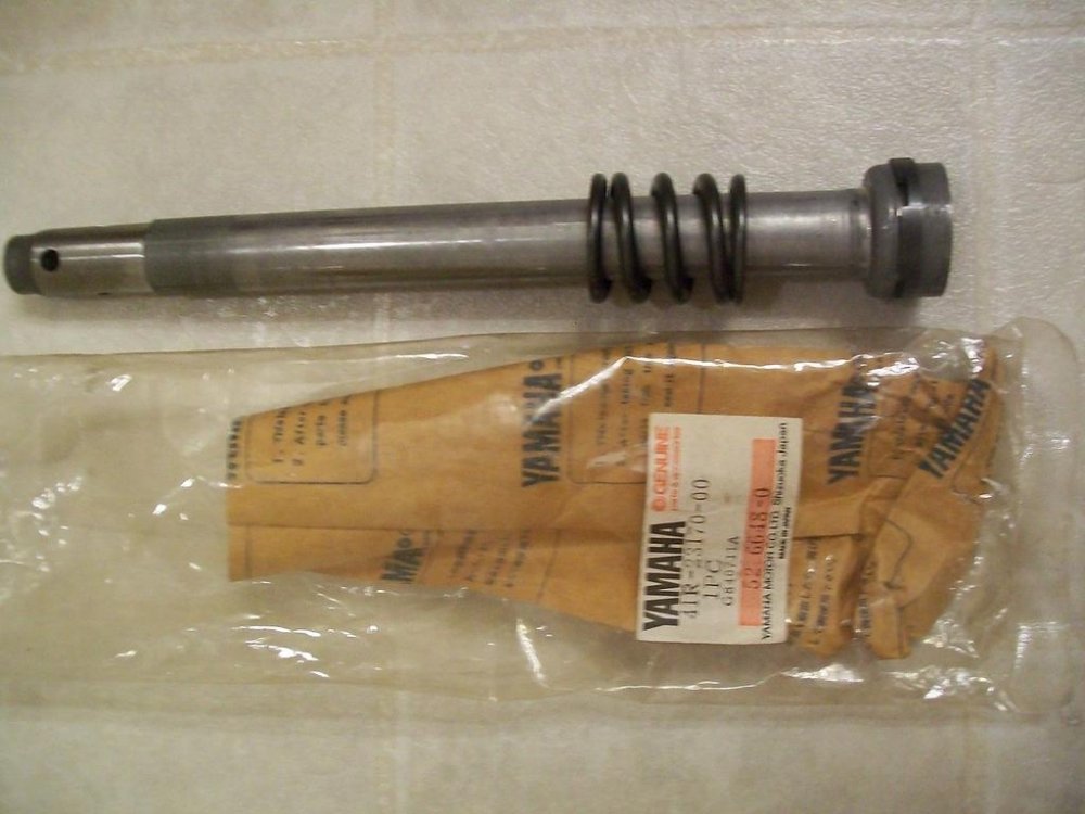
No. As I illustrated, they are supposed to be on the lowest end of the damping rod, but may have fallen off when you separated/removed the lower fork tube from the upper fork tube. The Allen socket cap screw that you removed from the bottom of the lower fork tube, secured the "plate, seat" (top hat piece), the oil lock, and the three washers in place at the end of the damping rod. When you removed the Allen socket head cap screw and slid the lower tube off the upper tube, the aforementioned pieces were now loose and unsecured to the damping rod and may have remained in the lower fork tube. Since the seat plate and oil lock are now on the damping rod in the picture, you must have retrieved them from the lower tube? Or did the oil lock and top hat stay attached to the damping rod? Since you removed the Allen head screw that held all those pieces together, I don't see how the oil lock and top hat could have remained on the damping rod. The "skinny tube" is the damping rod (or "cylinder" in Yamaha parlance). The top of the damping rod is fitted with an oil seal. The oil seal creates a friction fit with the interior of the upper tube. Simply pull the damping rod out of the upper tube. A picture of the "skinny tube"/damping rod/cylinder: Note that there SHOULD be a rebound spring as pictured. It is loose on the damping rod. -

Fork Overhaul
Prairiehammer replied to dna9656's topic in Venture and Venture Royale Tech Talk ('83 - '93)
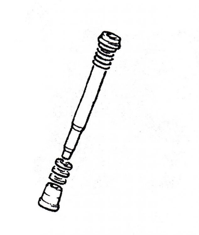
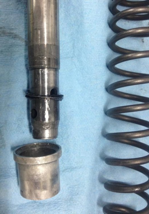
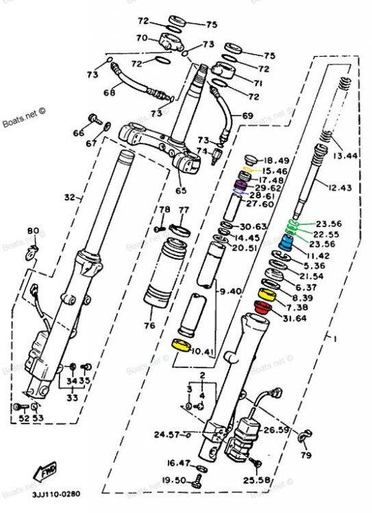
Doug, you haven't stated what year/model these forks are from, but since I see the "plate, seat" on the "cylinder" (more commonly called the dampening rod), you must be rebuilding the 1988 forks. The "plate, seat" was used on the 1988-1993 forks. That "plate, seat" is no longer available, so treat it gently. The rubber lip/seal on the "plate, seat" is easily damaged. While we are talking about the "cylinder"/damping rod, I should point out a couple things: Those three washers that are mentioned in an earlier post by you (26H-2319L-00-00 WASHER FORK 1 EACH SIDE, 26H-2319M-00-00 SPRING WASHER AKA WAVE WASHER**** ) are located above the oil lock aka "taper spindle", at the bottom of the cylinder/damping rod. There should be two wave washers (Yamaha calls it "Spring, valve" PN. 26H-2319M-00-00) with a flat washer (PN 26H-2319L-00-00) between them. This stack of washers acts like a valve spring for the oil lock, oil lock acting as a valve for the fork oil. Here are couple pics showing the three washers on the damping rod Please note that second illustration photo shows the oil lock upside down. Your pics of your forks also show the oil lock upside down. The spring, valve/wave washers 26H-2319M-00-00 are still available if you are missing any, but I would look for them still remaining in the lower/outer fork tube. The flat washer, 26H-2319L-00-00, is no longer available. This illustration is of a 1988-1993 fork assembly. Green items are the three washers (2 wave, 1 flat) that make up the stack acting as a valve spring for the oil lock. The oil lock is blue. The "Plate, seat" is red. The bushings are yellow. The lower "bushing", part number 3JJ-23171-00-00, (Yamaha calls it a "Piston") is still available from Yamaha and the normal OEM parts outlets, albeit not cheap. https://www.boats.net/product/yamaha/3JJ-23171-00-00 The upper "bushing", part number 3JJ-23125-00-00, (Yamaha calls it a "Slide, metal") is also still available from Yamaha, Partzilla, eBay, etc. https://www.boats.net/product/yamaha/3JJ-23125-00-00 I've never made bushings. In an earlier post in this thread from Earl, HE mentioned making the bushings. (I don't know why he said the bushings are no longer available.) -

Fork Overhaul
Prairiehammer replied to dna9656's topic in Venture and Venture Royale Tech Talk ('83 - '93)
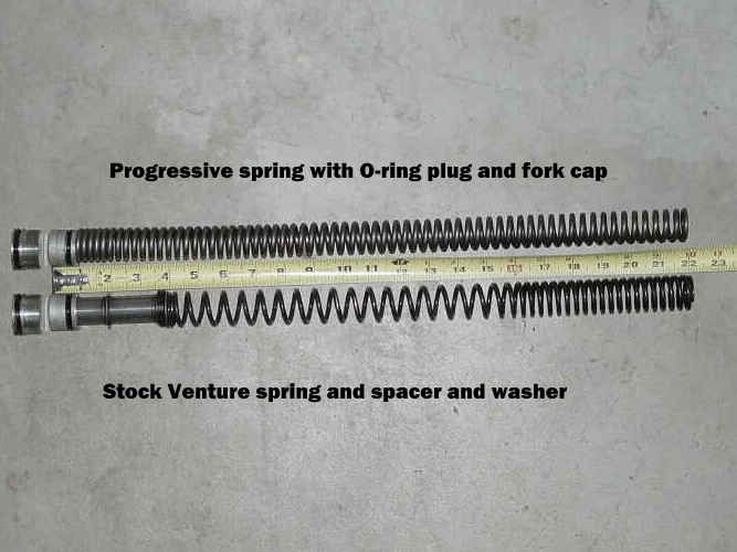
Doug, the stock Venture springs are somewhat "progressively" wound in appearance. Some folks categorize the stock springs as "dual rate". The Progressive® Suspension springs for the Venture are longer (thus negating the need for the stock spacer) and heavier gauge wire is used for a higher spring rate. Pictured is a comparison of stock springs and Progressive® springs as for a MKII Venture. Most have found the preload offered by the use of the stock aluminum plug under the fork tube cap is sufficient (no need to use any of the Progressive® supplied PVC spacer). All of this information is applicable to MKII forks only, the MKI forks have other needs. -
Justin, you sure picked a doozy of a question for a start. I don't know what the speedometer ratio is, but I know of at least a couple Ventures that are running non OEM speedos. @zagger . Justin, I thought you were going to retain the original Venture appearance? Replacing the instrument panel is gonna open a very large can of worms. I suggest you hold off on modifications until you get the Black Beastie running well, stopping well and riding well. THEN do some mods.
-

Teardown and rebuild into something a little more... Me
Prairiehammer replied to Loy's topic in Videos
Gary, be nice to the newbie. This is my old '83. As he delves into it, he will most likely be ragging on ME about something about this Venture. -
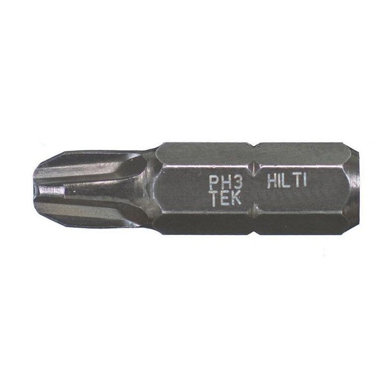
One does not have to remove the main fairings to remove the TCI from the stock location. Remove the air box and the lower fairing on the left side. Remove the black plastic "heat shield" over the front valve cover. Use a number 3 Phillips, one inch long insert bit, taped into a ¼" socket mounted on a short handled ratchet to get the two screws that hold the TCI to the coil rack.
-

Don't want to hijack the thread so I'll start a new one.
Prairiehammer replied to uncledj's topic in Watering Hole
My first gun, (I was 13 years old) was a Mossberg Model 185D, 20 gauge bolt action shotgun. That gun is also the most uncomfortable gun I have EVER shot. What a kicker! I still have it, and want to fix the magazine and put on a scope and a GOOD recoil pad. Load it with slugs for Illinois deer. -
Allen, your multiple photos are not in focus, but I THINK your VIN is 31H 000506? If so, your Venture is a 1983 XVZ12TK (Standard, non Royale Venture) intended for Canada. I've seen several examples of your "too short" VIN, all were originally registered in Canada. The 17 character VIN that your insurance company and registration entity seemingly requires, was not universally adopted by all countries in early (January?) 1983 when your Venture was built. It IS a valid VIN, though.
-

1st Gen LED Headlight
Prairiehammer replied to videoarizona's topic in Venture and Venture Royale Tech Talk ('83 - '93)
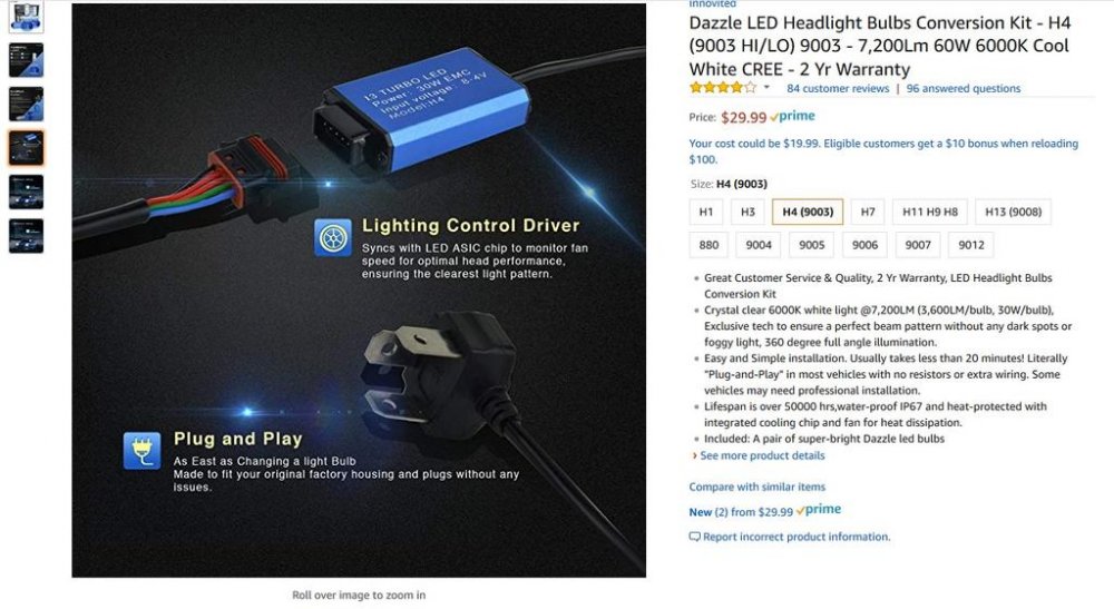
The blue box is the controller. I put an LED H4 bulb (a different brand) in my 1991. It had a cooling fan. Other than the rubber boot around the bulb on the original H4 not fitting, I had no issues with getting the LED bulb in. BTW, there is/was no 1993 Royal Star. And welcome to VRO as a Supporting Member greenbeenie. -

Exhaust Gasket Replacement?
Prairiehammer replied to luvmy40's topic in Venture and Venture Royale Tech Talk ('83 - '93)
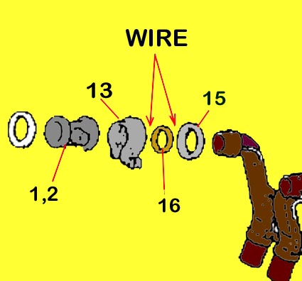
That copper donut was leaking on my 1983 back in 2002. I've done the repair with success. I found that 14 gauge solid conductor wire (as from Romex house wiring) worked well. Twelve gauge wire was too fat and made fitting the clamp difficult. Also, very important: the wire must be as long as the circumference of the pipe where you are trying to install it. If it is too long, then the wire ends will overlap and be too fat for the clamp. It is OK if the wire is SLIGHTLY shorter than the pipe circumference. When you get the clamp started tightening over all the pieces make certain that the copper wire is lying alongside the stock copper gasket and evenly within the clamp trough. You may find that after tightening the clamp and getting the exhaust pipe hot that the copper wire has softened and conformed to the clamp and pipe, necessitating some more tightening of the clamp. Keep checking the clamp and tightening for the first few rides. Finally the wire will fit very well inside. You can even install another 14 gauge wire to the other side of the copper gasket if needed. I did on #1 cylinder on my '83. Good luck with this repair. It can be done but it is admittedly a difficult space to access and work within. -

Second gear?
Prairiehammer replied to snyper316's topic in Venture and Venture Royale Tech Talk ('83 - '93)
YEP. Just for you. And it is only 100° here, 121° in the shop. No sacrifice too large for a fellow VentureRider. -

Second gear?
Prairiehammer replied to snyper316's topic in Venture and Venture Royale Tech Talk ('83 - '93)
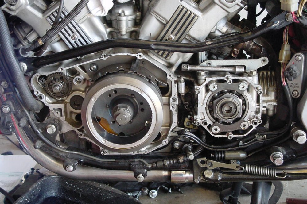
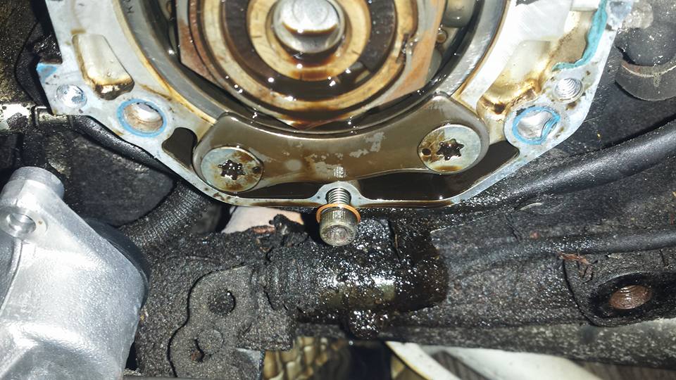
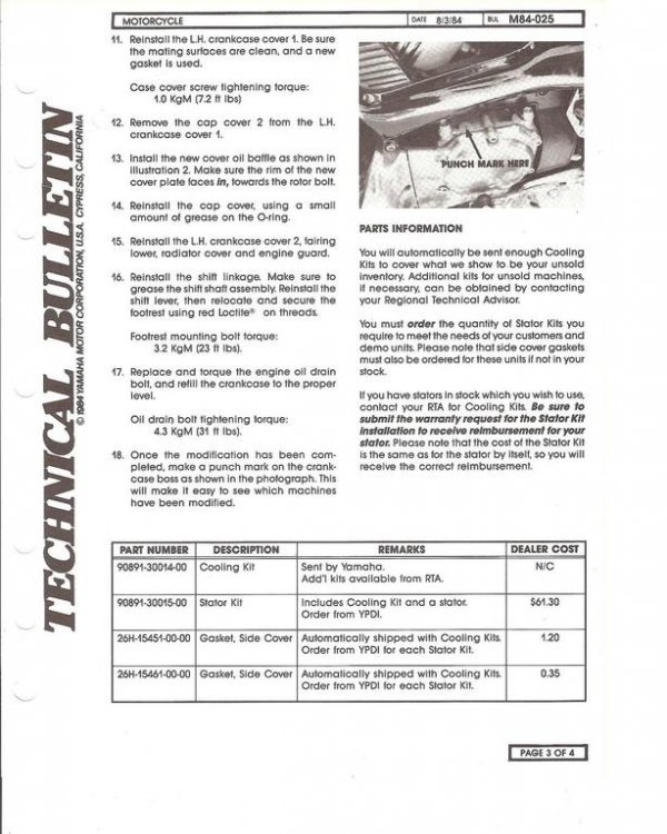
I am not sure what four bolts you are talking about, but I suspect you are talking about the four flat head screws with the Torx socket head under the middle gear cover that retain the middle gear retainer plate? If those bolts/screws are what you are wondering about, the "punch" marks on them are in fact staking the bolt/screw heads. The punch marks are made at the factory and do not indicate a repaired thrust washer. There was no dealer applied mark to indicate a repaired second gear. Replacing a worn thrust washer was not a warranty item. Furthermore, a repaired second gear procedure includes replacing the thrust washer and new spec second gear/dog. The "punch mark" that is so often talked about was to indicate that the stator cooling kit had been retrofitted. The single punch mark in that case was supposed to be applied by the dealer onto a smooth blank boss on the crankcase near the middle gear cover. M84-025 Stator Cooling Kit Installation.pdf -
-
I am not saying this is your problem since you indicate that the cylinders misfire erratically and not simultaneously, BUT a wonky IGNITION fuse holder may exhibit similar operation. Have you upgraded to ATC/ATO fuses from the stock, old and problematic fuse block?


