-
Posts
5,403 -
Joined
-
Last visited
Content Type
Profiles
Forums
Gallery
Events
Store
Everything posted by dingy
-

Shift Shaft Seal
dingy replied to dna9656's topic in Venture and Venture Royale Tech Talk ('83 - '93)
What bike is question refering to? http://www.venturerider.org/forum/watering-hole/90684-help-help-bike-info-header-updated-forum.html I have a new seal for a 2nd gen I don't need. Gary -
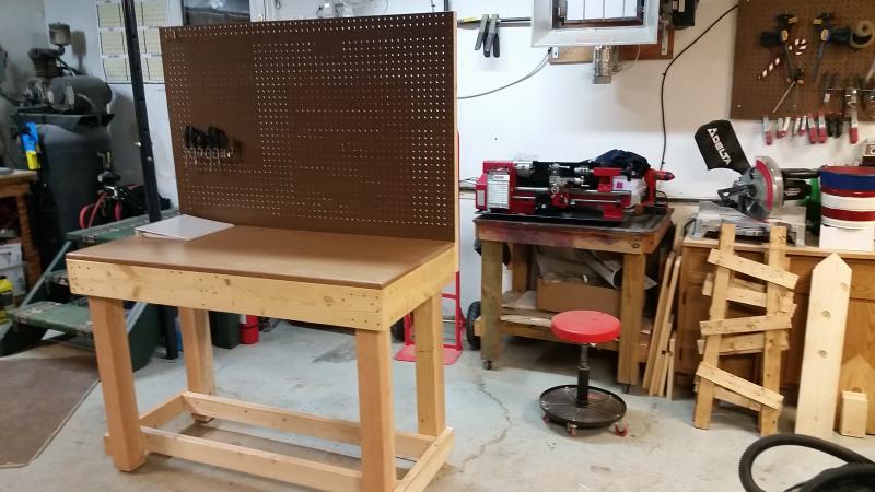
https://www.grizzly.com/ is web site for grizzly, similar to littlemachineshop.com Found TES joke while I was looking for new tool that will be here Wednesday. It's home will be on new table in foreground, somewhat related to tool to right of new bench. What do you think it will be ??? Gary
-
Tool Envy Syndrome (TES) Tool Envy Syndrome (TES) is a serious condition that afflicts, in varying degrees, nearly all men who are interested in mechanical things. It is very important to recognize and deal with this condition before it becomes serious; left untreated it can lead to a far more serious condition: Inflammation of the Credit Card (ICC). TES is known to strike under the following circumstances: Browsing the latest tool catalogs or sale flyers Visiting stores such as Grizzly or Harbor Freight (Warning: while much less so than in earlier years, the tool department at Sears can still trigger small attacks) Visiting the shop of a friend who has more and/or better tools than you have Surfing the web site of someone with a well-equipped shop Seeing a well-equipped shop in magazines such as Home Shop Machinist Tool Envy Syndrome tends to strike young men particularly hard, due its close relationship to a similar condition: Gear Acquisition Syndrome (GAS). Over time, in most men, both of these conditions tend to lessen in severity. In fact, it can be shown that gradual accumulation of tools and gear over a period of years can control both conditions while minimizing the risk of Inflammation of the the Credit Card (this is known as the Mature Phase). It has also been widely observed that getting married and having children can moderate the risk; primarily, it is believed, due to counseling from a loving wife and the sobering effect of having lots more bills to pay. Tool Envy Syndrome cannot be controlled by any known drugs (although its effects can be exaggerated by the use of alcohol). Therefore, treatment is currently limited primarily to counseling methods. The first step is admitting that you have a problem. Here are some additional pointers: Avoid situations that are likely to cause an attack When visiting tool stores, leave your credit card at home (Warning: in severely afflicted individuals this can trigger emotional breakdown, fits of crying and other irrational behavior) Meditate on the fine collection of tools that you already have; recognize that time will make it better Find a quiet place. Visualize your ideal shop. Repeat to yourself "It is coming" I hope you have found this information to be helpful. As a TES/GAS sufferer myself (now in the Mature Phase) I felt compelled to pass it on to you.
-
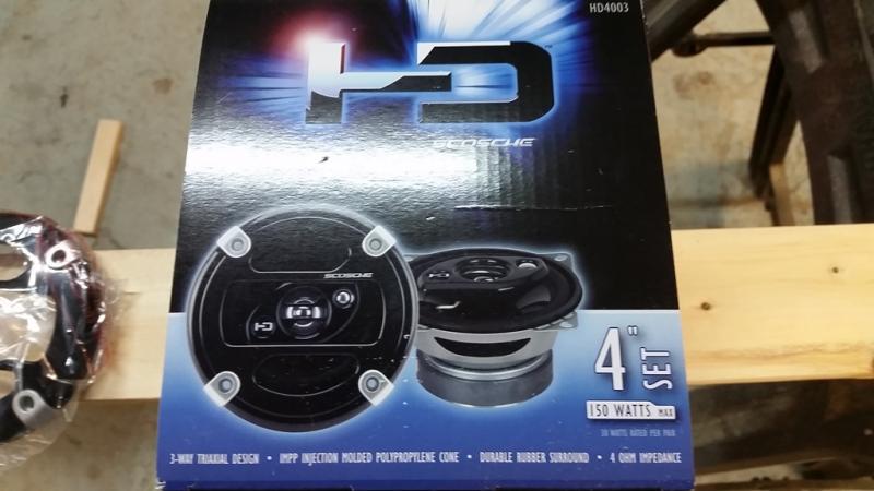
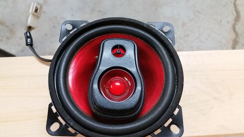
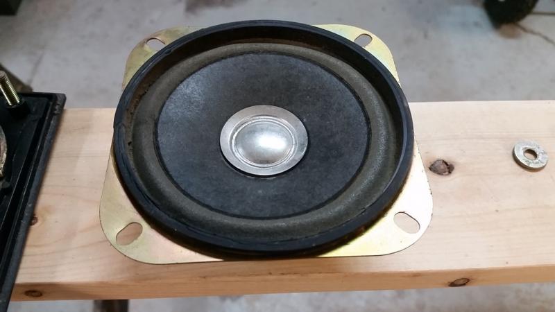
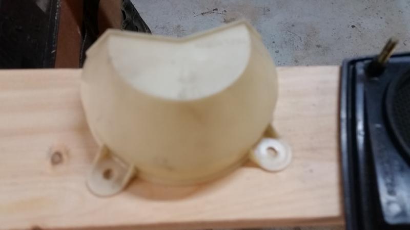
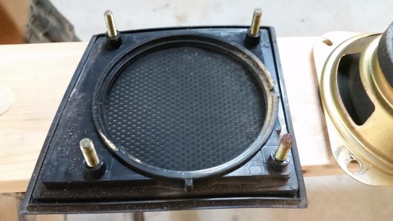
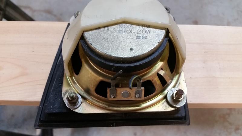
Attached are a few speaker parts. Old speaker is stock, red one is the wal-mart unit I had it in Tweety for a couple of years. Picture of box is what I have in Tweety now. Scosche is mfg. HD4003 is p/n. Rear cover won't fit on with these. I don't think these are waterproof, I put saran wrap over them, below outer cover. Gary
- 9 replies
-
- appreciated
- bolt
-
(and 3 more)
Tagged with:
-
4 nuts on inside of fairing, studs in cover go through speakers, then through console panels . Do no over tighten nuts, or you will pull stud out of radio cover. 4" speakers are all that will fit. Wal-Mart had a decent set, 3 way speakers for about $30 at one time. Gary
- 9 replies
-
- appreciated
- bolt
-
(and 3 more)
Tagged with:
-
Was Freebird visiting you recently? Gary
-
Some may think not hearing the passenger was a feature !! Gary
-

Front fork position
dingy replied to Venturous Randy's topic in Venture and Venture Royale Tech Talk ('83 - '93)
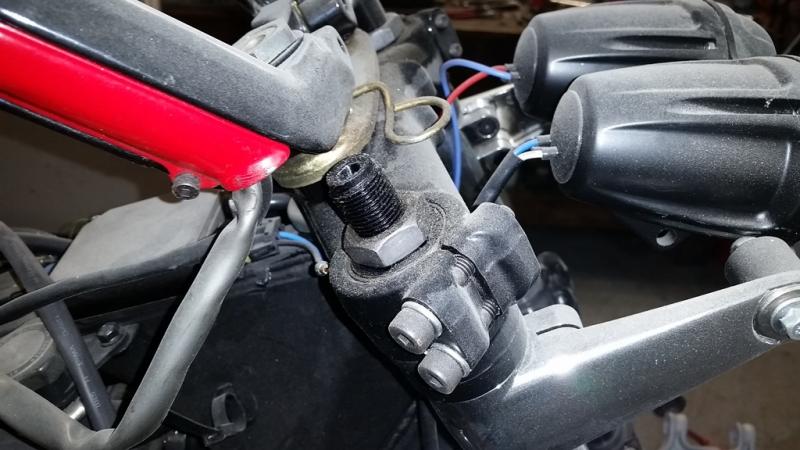
On a more practical note, you might be able to plug holes with JB weld, then file residue down smooth to block air ports, they are rather small. Guessing maybe 3/32" dia. You won't be able to raise forks much, maybe 3/4" before you have clearance issues with fairing. Then as mentioned above, you will run into clearence issue with fork brace when front end is full collapsed. Front end has 5 1/2" travel. I have a set of adjustable fork preload caps that wouldn't fit on Tweety, they are on Hybrid for now. Picture shows them, bike is dusty from where I blew insulation into garage attic & sidewalls a few weeks ago. Gary -
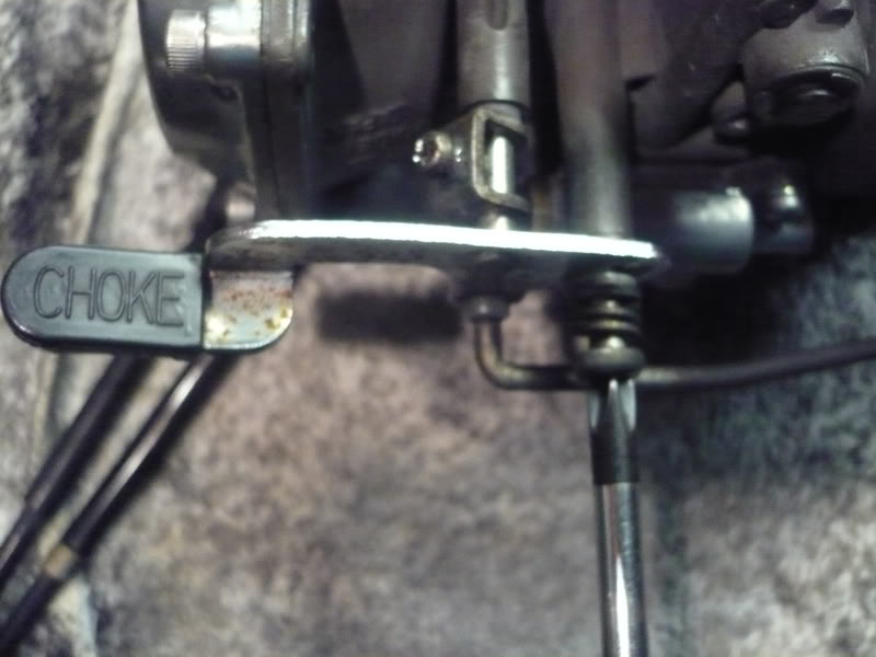
The 83-85 Ventures are 34mm venturies, The 86-93 Ventures are 35mm. All 1st gen VMaxs are 35mm. Another somewhat large hurdle is the left front carb on the Ventures does not have a 'boss' on the casting that the VMax's do. This is where the choke lever mount attaches, it is a must have to use VMax choke. As Squeeze said, jetting is also quite different. Picture is of carb rack upside down, lever screws into the long boss that goes off picture to the top. Screwdriver is into screw from bottom of picture. If you try to use Venture setup, then you need to install a cabled system that is connected to left hand grip housing. I have modified 2 sets of Venture carbs completly to VMax specs, on both I replaced the left front carb body, and put $300~$400 in new parts to get them in good shape. Gary
-

Front fork position
dingy replied to Venturous Randy's topic in Venture and Venture Royale Tech Talk ('83 - '93)
No, but I bet you had the cursor over the "LIKE" button. Gary -

Front fork position
dingy replied to Venturous Randy's topic in Venture and Venture Royale Tech Talk ('83 - '93)
Just offering suggestions to help you get the most out of your Venture. Gary -

Front fork position
dingy replied to Venturous Randy's topic in Venture and Venture Royale Tech Talk ('83 - '93)
High Heels may be the easiest. http://i1007.photobucket.com/albums/af193/gdingy101/heels_zps8609e308.jpg You may prefer more of a platform style. Gary -
If the warranty replacement is denied, you might check out post #10 in thread linked below. http://www.venturerider.org/forum/second-generation-venture-tech-talk/92128-pbjmans-thread-fuel-pump-rebuilding-gravity-feed-cheap-ebay-fuel-pumps.html#post879351 Gary
-
Mine is a nickname similar to my last name which is Dinges, pronounced like door Hinges, but with a D. Nickname is pronounced as in Ding dong, with a Y on the end, same as the small boat Dinghy. For those that know me, Dingy fits my personality. Gary
-
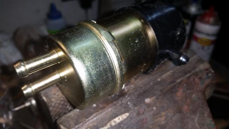
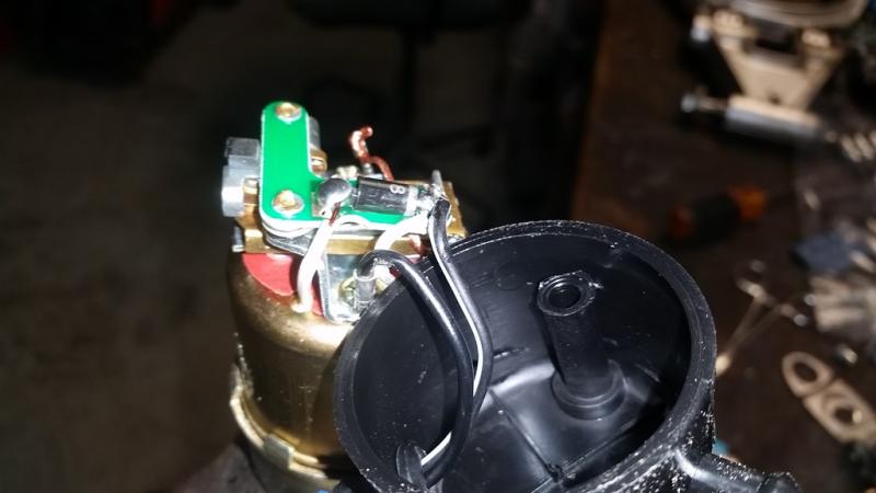
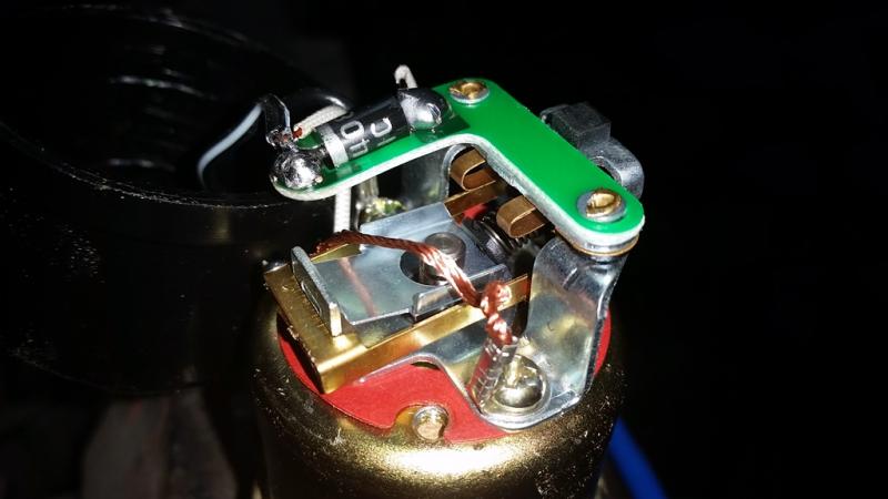
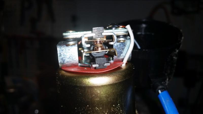
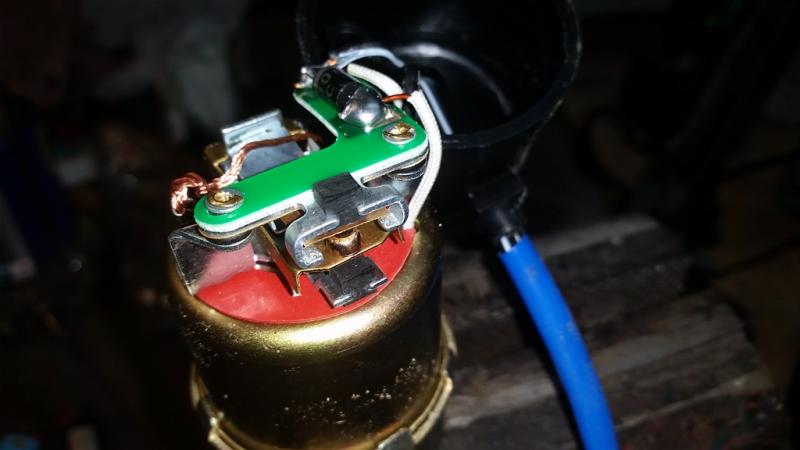
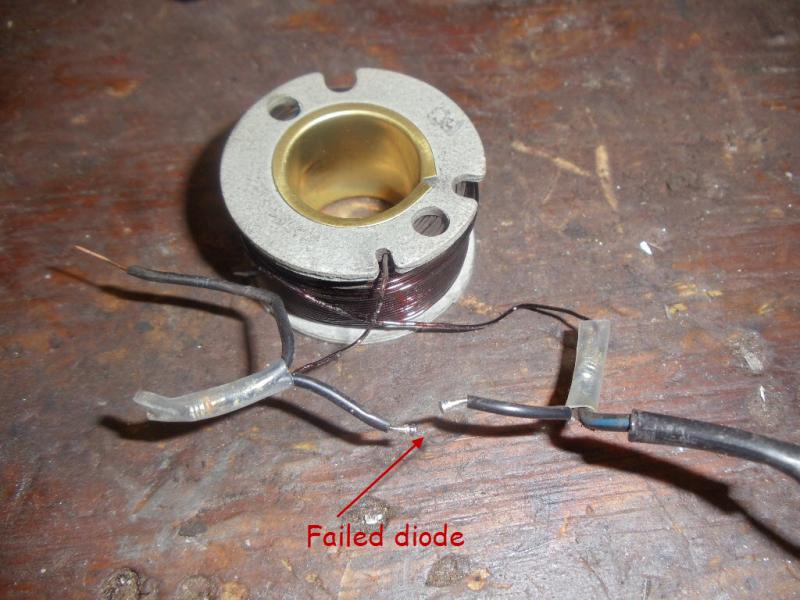
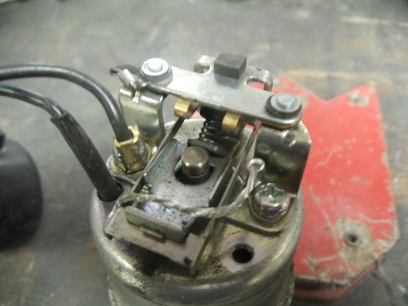
I ordered one of the RSV replacement fuel pumps and it came with the needed 8mm fuel ports on it. Cost was $24.77 with shipping included. Shipping was fast. Some pictures attached of the electrical end of the pump. It is almost the exact same layout as a stock RSV pump with one very good exception. The diode on the stock pump is much smaller and is located near the coil, the replacement unit has a much larger diode and it is in the electrical end where it is easier to replace if needed. The ebay sellers ID is ultimatecomponents. Hover cursor over links and click., they don't seem to highlight since site upgrade on my computer. Listing for current auction is New Fuel Pump for 1996 2009 Yamaha XVZ13 XVZ1300 Royal Star 4NK 13907 00 00 | eBay Couple of pictures of stock RSV pump I dissected also attached, one has failed diode pointed out. Gary
-
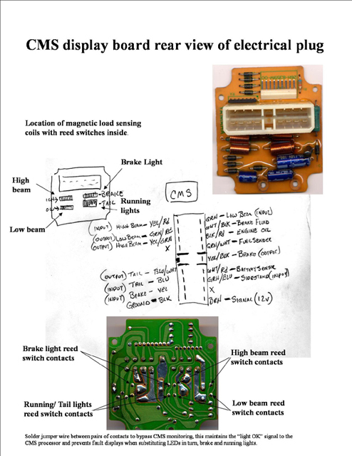
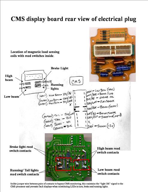
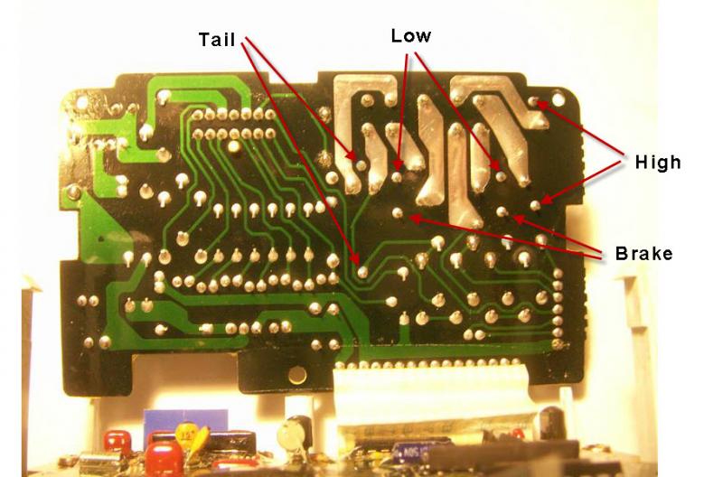
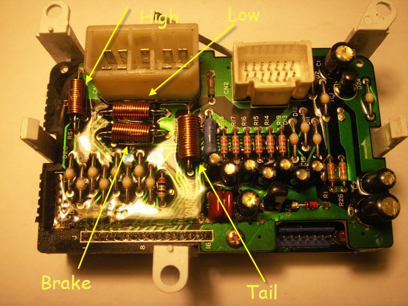
It appears you have 83-85 Ventures looking at your profile. The 83-85 CMU is different than the 86-93 CMU. I don't have a picture with the jumpers shown. What I have is attached picture that shows location points for the jumpers though. It was done several years ago by a member here. You would solder a light gauge wire, probably about 18 gauge, between each of the points noted. This will be 4 separate jumpers. One end of each going to the circuit board terminals called out. I sketched them in red highlight. One picture without highlighted jumpers and other with them. Gary
-
I think attached pictures are what you want. These pictures are of an 86-93 CMU, 83-85 CMU's are different. See post #12 below for the 83-85 version. The 'probe' suggestion earlier is for the battery warning indicator. Soldering the jumpers shown will eliminate CMU from warning for the high & low beam. Other pictures show jumper positions for brake & tail lights. Gary
-

1st Gen Starter clutch repairs
dingy replied to Dano's topic in Venture and Venture Royale Tech Talk ('83 - '93)
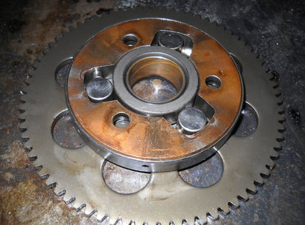
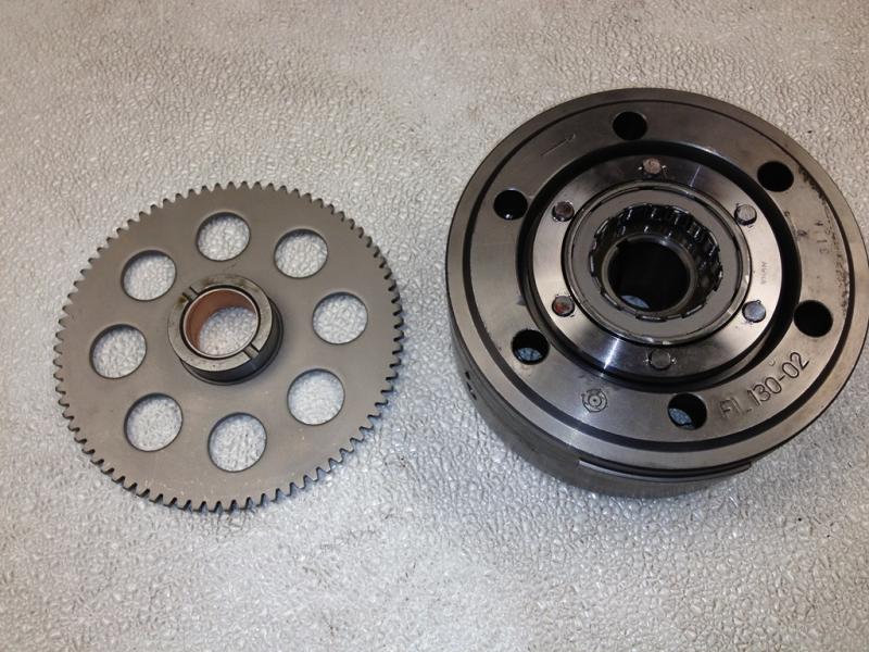
Dano's fix for the starter clutch is excellent. It will permanently fix the starter clutch issue. Original starter clutch removed from rotor. Dano's modified clutch installed in rotor. Also included is new idler gear. Gary -

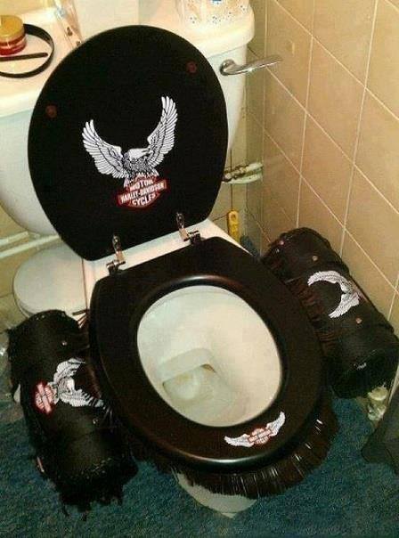
Paparazzi snaps picture of Freebird’s Harley when he snuck out for a ride..
dingy replied to KIC's topic in Watering Hole
-
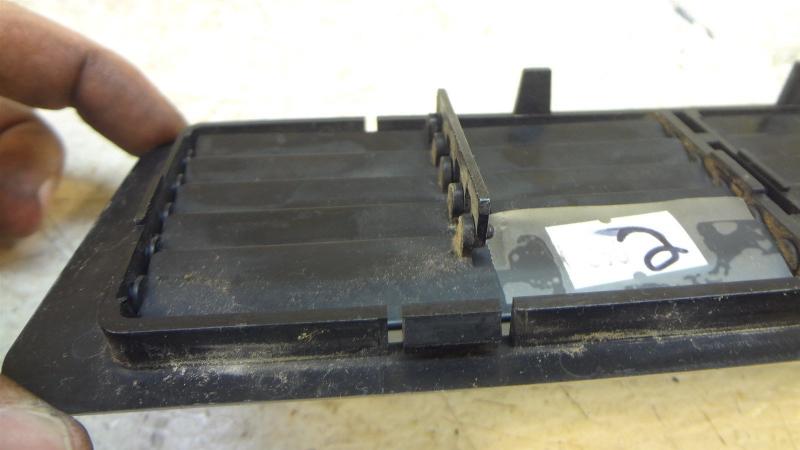
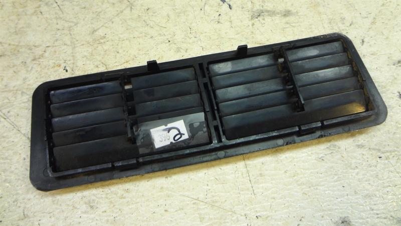
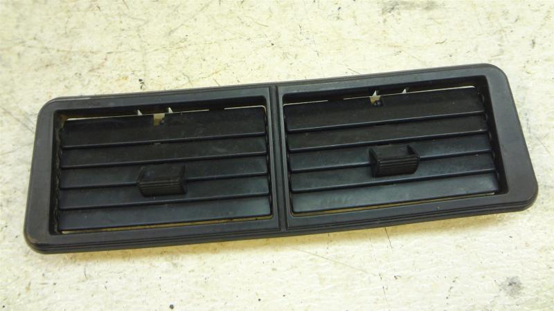
3D printing for this part is probably not a good option. I have a high end 3D printer at work that I am primary user of. Upside of the printer we have is it has dual material capability in same run, so some materials can be blended, within programming limits of software to create different grades of materials similar to plastics.It will make materials from rubber band rigidity through ABS similar rigidity. Problem for this application is two fold. 1st, with machine I have access to, the heat rating is to low for heat part would be subject to. Maximum temperature of an SLA (stereo lithography) based machine maxs out at about 175 F. Secondly, almost all 3D parts are fairly brittle, or prone to tear in softer durometer materials. FDM (fused deposition) models will have a better high end heat range, but they are not very good at producing small details on parts. FDM machines use a spool of filament, which is melted in very small amount, thousands of times and deposited on base plate to create part. I have dealt with Protolabs on a number of plastic injection molds. They are a not a high end operation. Their costs are very high. If I need any modification to a mold, charge started at $1,000 just to start work on mold and went up from there, regardless of how minor change was. There base charge to set a mold in machine is $500. They do not even want drawings, all they will accept is a 3D model, preferably STP format. This means they do not attempt to hold any close tolerances in parts. I don't recall what there generic tolerance is, but I know it was a sliding scale. The larger the part the higher the standard tolerance would be. I will not deal with them again and have found better & more production oriented mold producers. One of the factors that will make this cost prohibitive for an individual to pursue is the need for 3 separate parts to do this. Assuming the low potential volumes that would be sold, and by low I mean a run sufficient to do 250 individual vent assemblies with 4 assemblies on each bike. The 3 separate parts is an issue because one part there is a quantity of 4 needed. The other 2 parts only have 1 each used on an assembly. There are 2 different configurations of the vanes, and another part for the connector bar. The mold could be designed so as to include a cavity for each of the 3 pieces, with a shutoff gate in feed lines for each part, or at least the 2 that only one is required. This would enable mold to be ran so as to only fill parts needed on each run. I believe the mold halves have to be pulled from machine to reset the shutoff gate as they are inserted from back side. Where it starts to get tough is material selection. I don't think ABS is what these are made of, due to flexibility needed to insert parts into outer housing that holds the vents and snap connector bar into place. Material choice is critical to these parts as they need to be somewhat pliable and able to with stand relatively high temps. So then material chosen may not be something molder has in inventory, minimum material quantity purchase are standard. A normal size bag of material is the size of a standard pallet and about 3 feet tall, 1500 lbs, way to much. Material required for 250 sets would be in 50-100 lbs range. You are going to pay dearly for this amount. That's the readers digest version of why I don't think an individual is going to invest the money required just to get the tooling to do this. 3D printing is a great way to make a prototype or a limited run of parts. Issue with 3D printing is it is very slow, thus expensive. An injection mold machine for a part this small may have a cycle time of 20 seconds shot in the mold. A 3D printer will be far slower than that, possibly in excess of 10 minutes per part. The parts of of a FDM printer have a rather course finish to them, nowhere close to an injection part. Surface finish can be improved by dipping parts in acetone. 3D SLA parts have a better surface finish, but require a cleanup operation after printing to remove support material. Them a treatment in a 2% lye/water solution to remove film from surface if part is going to be painted. The use of a 3D scanner for something like this is probably less than optimal as reasonably priced scanners have a resolution in the .010" to .020" range. While fairly small, it is not quite what is needed for these parts to fit together right. Jeff's suggestion for just manually measuring part would be my 1st choice. So assuming a conservative guess of $3,000 for mold, another conservative guess of $4.00 per vent assembly. Then assuming 250 assemblies were ordered, that would be about $16 per assembly, without shipping charges for initial order. That would then translate into $64 for the four required vent assemblies. That is base cost, now factor in design time, transportation to you, then to end user, taxes, etc. If anyone wants to create CAD design and do this, I can furnish web site for an offshore (China) molder that has a decent online estimator system that will give a fairly accurate quote. They can deliver samples usually in 3 weeks. The above is my day job. I design & source small plastic (usually) housings for a new product development group in the Emerson Electric group of companies. I have 3 in jobs progress now that will require about 10 separate molds. I'm the mechanical design engineer. Bunch of other people design the sensors that we are bring to market. Gary
-
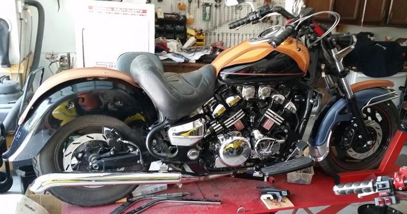
Picture is from a 2003 RSV frame I am using to build a hybrid RSV/1st Gen/VMax/RSTD bike from. Slow progress on it, but it is getting there. Gary
-
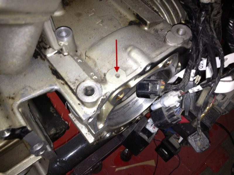
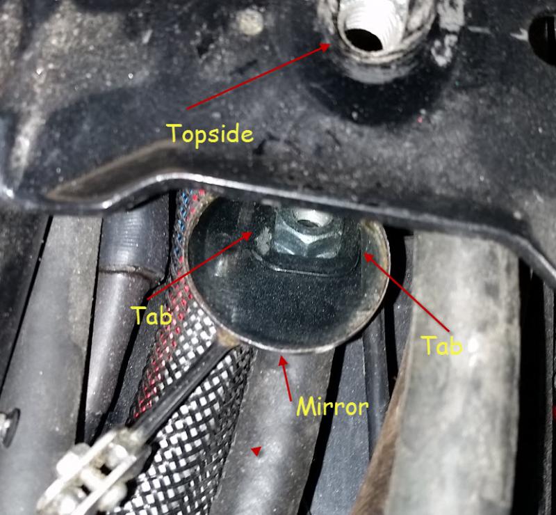
Don't know if this will help, but attached picture is best I could get of nut. Topside arrow is looking at hole bolt goes through, threads in nut are visible. In reflection in mirror, there are 2 tabs on either side of a steel plate that the nut slides into. This is not the stock nut shown, I had same problem you have and I cut head of bolt off and replaced with a flange nut. Gary


