-
Posts
5,403 -
Joined
-
Last visited
Content Type
Profiles
Forums
Gallery
Events
Store
Everything posted by dingy
-
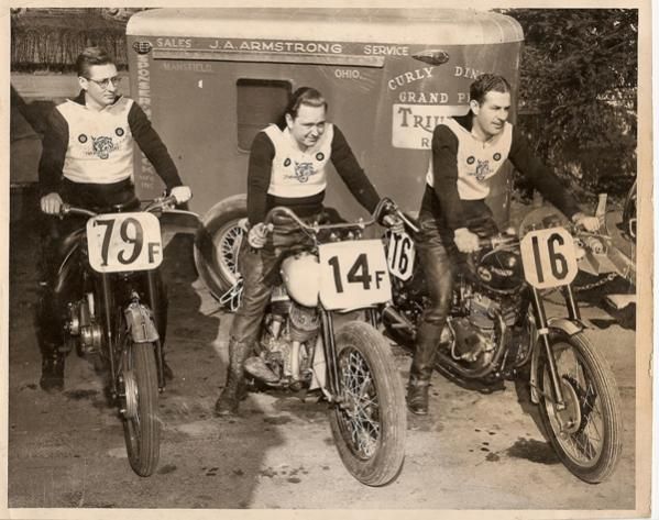
Fine looking group of young men. Unfortunately, my family is going to bury an young man that died in Afghanistan this weekend. My grand nephew was killed by IED. http://www.patriotguard.org/Forums/tabid/61/postid/1246726/view/topic/Default.aspx Gary Semper Fi
- 17 replies
-
- afghanistan
- boys
-
(and 3 more)
Tagged with:
-
Copy would be fine or a scan would work also. If you scan it, check to see that text is legible. Don't worry about getting the wire color chart in scan, I can do that chart from memory at this point. My schematic was a little long to scan in chart. If you want to mail it to me, I'll PM my address to you. If someone has an 84-85 Venture Royale schematic I could use it as well. My 83 schematic has Model XVZ12TK in top left corner. Anything other than this would be very helpful. Thanks, Gary
-
What I need for the 90-93's is a schematic I can read. Is there one in the back of the owners manual like my 83 has? Gary
-
I have completed the initial pass on the 1986-1989 model years schematics. My goal in doing this is to make them easier to read and reduce the number of pages needed to display the information. I have used color and line types to make the wiring easier to follow. In some cases I could not use the exact color that is being represented due to visibility and printing issues. For example yellow is hard to see on the screen and does not print well. I have tried to check these as thoroughly as possible. Any errors, corrections or additions that anyone has, please send to me and I will update the files. I have been assisted by fellow member Ozlander with his help checking over my work. I do not have a bike to look at to verify some of this info. I have an 1983 without Cruise or CLASS systems that varies somewhat from the 1986-1989 models. As I update these files I will increment the revision letter at the end of the file name. The files will look best when plotted at 11" x 17" size or larger. Office Max and Staples as well as others can do this for you for a minimal charge if you want a printout. I paid $1.00 for an 11" x 17" color print at Staples. There are four different PDF files for the schematics and one with some reference information from the service manual. To open the PDF file, click on file name shown in blue below. 86-87 Yamaha Venture DS Wiring Diagram Rev A.pdf 1986-1987 Venture XVZ13DS/DSC From 1986-1993 Yamaha Venture Service Manual, page 8-41. PDF file pages #467 & 468 of 496. This file combines the CLASS & Cruise systems on page #1, page #2 is the Audio system. 88-89 Yamaha Venture U Wiring Diagram Rev A. pdf 1988-1989 Venture XVZ13U/UC From 1986-1993 Yamaha Venture Service Manual, 1988-1989 Supplement. PDF file page #478 of 496. This file combines the Cruise systems on page #1, page #2 is the Audio system, page #3 is CLASS system. 88-89 Yamaha Venture DU Wiring Diagram Rev A. pdf 1988-1989 Venture XVZ13DU/DUC From 1986-1993 Yamaha Venture Service Manual, 1988-1989 Supplement. PDF file pages #477 & 479 of 496. This file combines the CLASS & Cruise systems on page #1, page #2 is the Audio system. 86-89 Yamaha Venture Simplified Circuit Diagram Rev A. pdf 1986-1989 Venture XVZ13DS/DSC - U/UC - DU/DUC From 1986-1993 Yamaha Venture Service Manual, page 7-1 thru 7-4. PDF file page #265 thru 268 of 496. This file combines the CLASS & Cruise systems on page #1, page #2 is the Audio system. 86-93 Yamaha Venture electrical info.pdf 1986-1993 Venture XVZ13DS/DSC - U/UC - DU/DUC - DA/DAC This file is a compilation of various sheets from the 1986-1993 Yamaha Venture Service Manual that would be helpful when working with the electrical system. They are not modified in any way, just as they appear in service manual.
-
From the album: Family bike pictures
-
From the album: Family bike pictures
-
From the album: Family bike pictures
-
From the album: Family bike pictures
-
I would like to have the Kilo speedometer, would make me think it went even faster !!
-
Does anyone have access to a readable copy of the 90-93 wiring schematic. The one that is in the 86-93 service manual is unreadable. I am nearing completion of redrawn schematics for the 86-93 models similar to the one I did for the 83-85 models. I can see that the three major changes to the 90-93 is the pick up coil change, fuel pump control relay & TCI unit. I need a readable schematic to get wire colors correct. Gary
-
Here is a link to a schematic for the 83-85 that is easier to read. Possibly bad canceling unit. I do have a schematic of the flasher relay done now if that would help you. Its more than a standard auto type flasher. [ame=http://www.venturerider.org/forum/showthread.php?t=40948]Updated easier to read 83-85 wiring schematic - VentureRider.Org[/ame] Gary
-

Remove instrument cluster
dingy replied to nitespecter's topic in Venture and Venture Royale Tech Talk ('83 - '93)
Attached is a picture showing two 10mm cap screws that hold cluster in place. They are just above the 45 deg angle in the bulb bracket in picture. Use a long extension to reach. You will also need to remove windshield. There are two screws on each side. Gary -
How hard was the pin stripping to get off ? Did you sand stripes all the way down or use chemical to remove ? Dingy
-
I started another thread so if any one had downloaded prior versions they would see the update. With help from Ozlander I believe that this is about as good as I can get this schematic. I have added the internal wiring on relays & rectifier. Added coil resistance on relays, generator & ignition coils. Added ignition coil #'s and location on bike. Added bulb p/n's. Cleaned up the wiring in handle bar switch area some more. Overall I have eliminated as many wire crosses as I can. Electrically, this matches what is in the owners manual. I didn't show internal wiring for flasher relay as it is fairly complex, not just a standard flasher. This looks best at 11" x 17" size. Office Max or Staples can print in color at that size for about a dollar. Dingy
-
Probably won't work on newer ones. Brazed a nut to the handlebar nut. Heavy Duty velcro. saw similar idea on here or other web site. They had used a coupling nut in place of handle bar nut. This nut is odd size, could not find coupling nut that would work. Radar detector mount is made out of two old mirrors cut & brazed together and a new mounting plate.
-
Here are a few pictures showing my first Venture. An 84 Royale. Chrome turn signal covers, master cyl. rear pig, drive shaft housing, kickstand, center stand, levers, rear foot peg brackets, swing arm, side cover parts. Wish I still had this one.
-
I just checked my 83 Venture with an ohm meter, and the brake circuits are Normally Open, as sitting in bike. The circuit closes when I pull brake lever. Did not check clutch. I would term this a Normally Open contact since as it sets in the bike it is N.O.. Granted when the switch is out of the bike & you bench tested it it would appear Normally Closed. Which designation is more accurate ?? I will work at adding relay circuits, but some may be difficult as I don,t have a canceling unit to open up. Sidestand, fuel pump, fan & starting relays are straight forward. Won't be able to do much with the reserve lighting, gauge panel or ignitor as they are all electronic. I think I saw a wiring for the rectifier/regulator on this site or somewhere, if some one has one handy, please send it to me. Don't have any idea on the pressure sensor other than a normal switch behind a diaphragm. I will change nomenclature on Front, Rear brakes & Clutch to Pull/Free. Sidestand I had revised to Up/Down, it was Push/Free which confused me. I will add coil info Ozlander furnished. Dingy
-
FrankD gave me a correction to the coil pickup wire colors. The common wire to the coils is Black, not Orange as original schematic shows. The black wire is still used, just not common. Also changed shape of the coil pickup wire connector to match what is on my bike. Schematic in original post updated to Rev C Thanks Frank Dingy
-
I have reloaded schematic in my original post. Now named Wiring Diagram Rev B I was partially wrong about key switch having five wires. My 83 has four wires. Bike does not have CLASS system. I have an extra key switch & wiring harness from an 84 Royale, these both have five wires. The service manual shows in the supplementary area a fifth wire with the CLASS system, it's a Red/Blue color. I received an 86-93 service manual from Ozlander and saw how its was formatted. I made more changes to clean this one up more, especially in regulator-generator area. Also in lower right by Brake fluid level sensors. I added N.O. (Normally Open) or N.C. (Normally Closed) by most of the switches. By some of the connectors, I have put a letter in parenthesis to indicate color of connectors. Went to Office Max last night and they printed a color print of this for me for a dollar. Staples can also do it. Just take PDF file to them. If you want me to I'll send you one for what it costs me. Large envelope is a dollar, print is a dollar & postage. About 3 dollars total.
-
I am finding numerous errors in what is shown on the original schematic as compared to what is on my 83 bike. One is there are five wires coming out of key switch, schematic shows four. Another is the side stand , fuel pump relays, fuel pump, fan motor & rectifier do not show black wire as ground, when it is. I will post another PDF when I get some of this traced out this weekend. Dingy
-
I have a copy of the 86-93 wiring now. It looks way better than the 83-85 one. I will work on putting some line types in it. I am going to work some more on the one I did to clean it up some more, now that I have seen 86-93 schematic and some of the things done on it. Ignition coil info would still be nice to add if anyone has it. Dingy
-
If someone will send me a scan of one I will work on it. This did take some time to do & check. Dingy


