-
Posts
1,190 -
Joined
-
Last visited
Content Type
Profiles
Forums
Gallery
Events
Store
Everything posted by Bert2006
-
:sign yeah that:
-
EH! We have snow and a few rain storms and the rare hurricane on the east coast. Will take that above tornados, hurricanes and other stuff you guy's deal with south of the border year long, but man this past winter has been a long one. Retiring in 8 years and looking into the snowbird options for us in either Florida or Arizona:cool10:
-
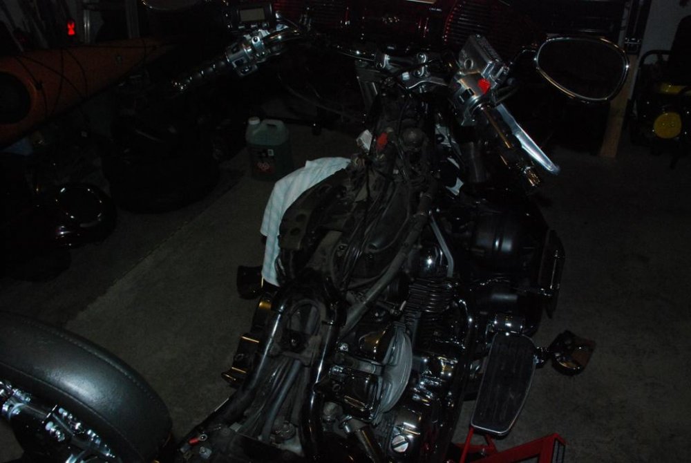
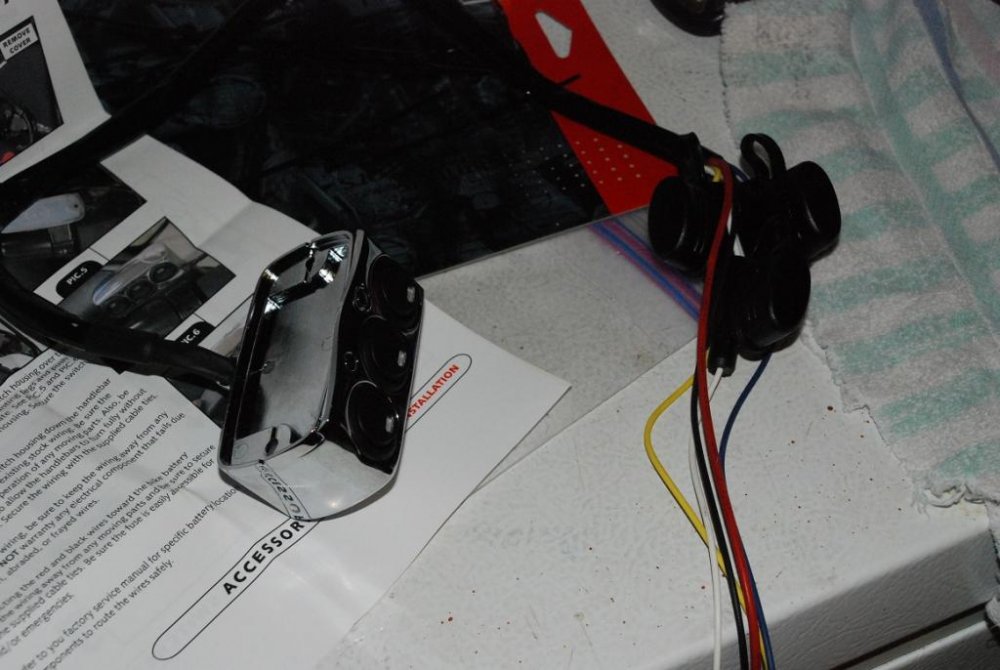
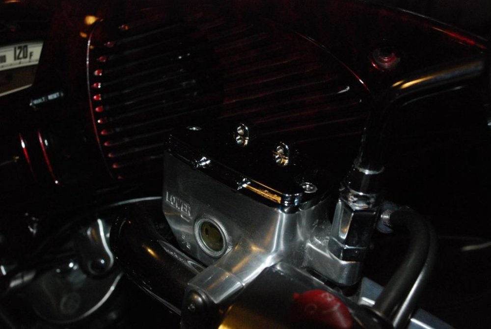
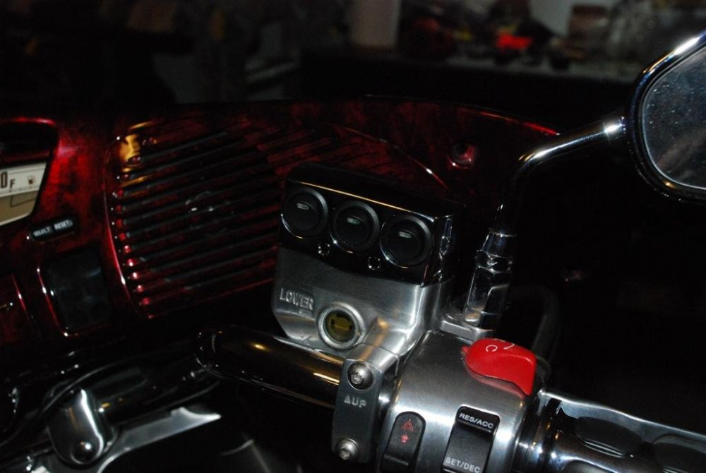
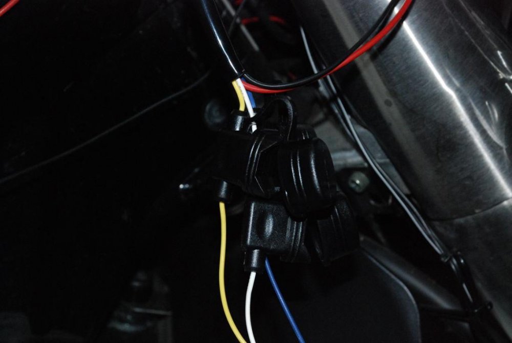
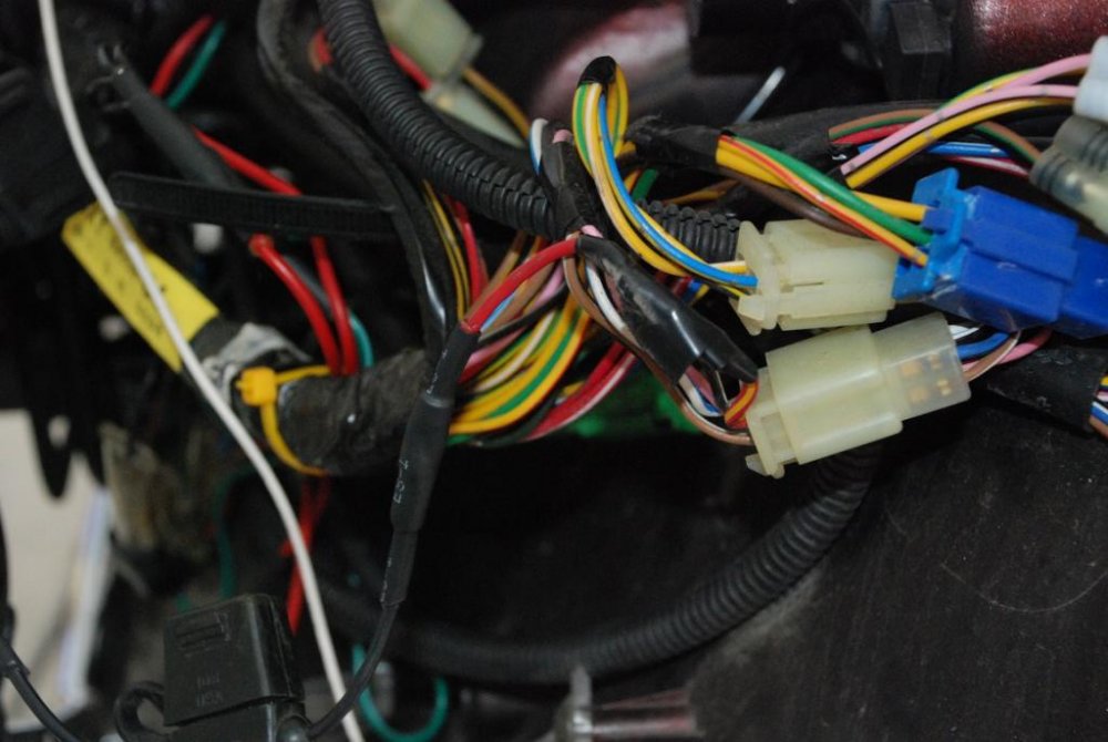
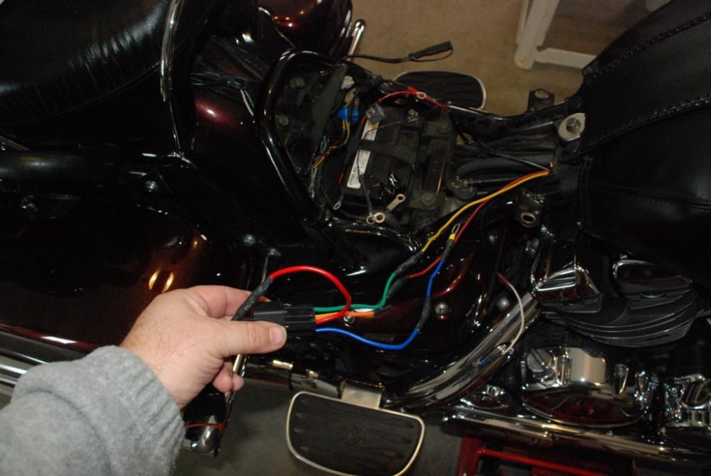
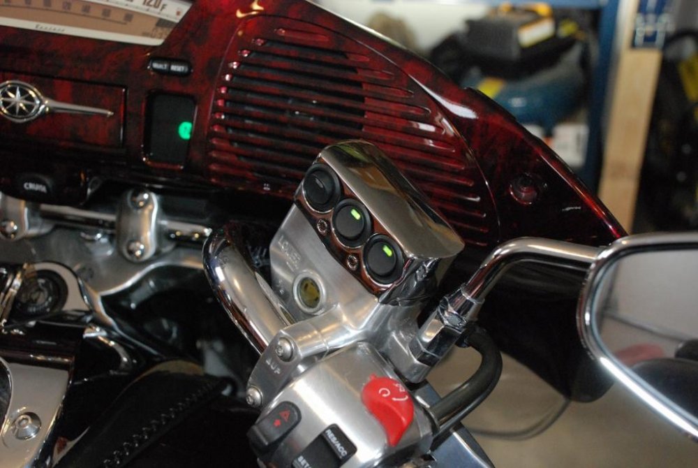
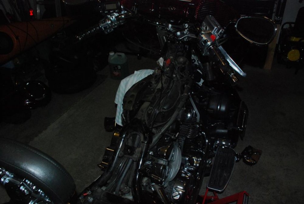
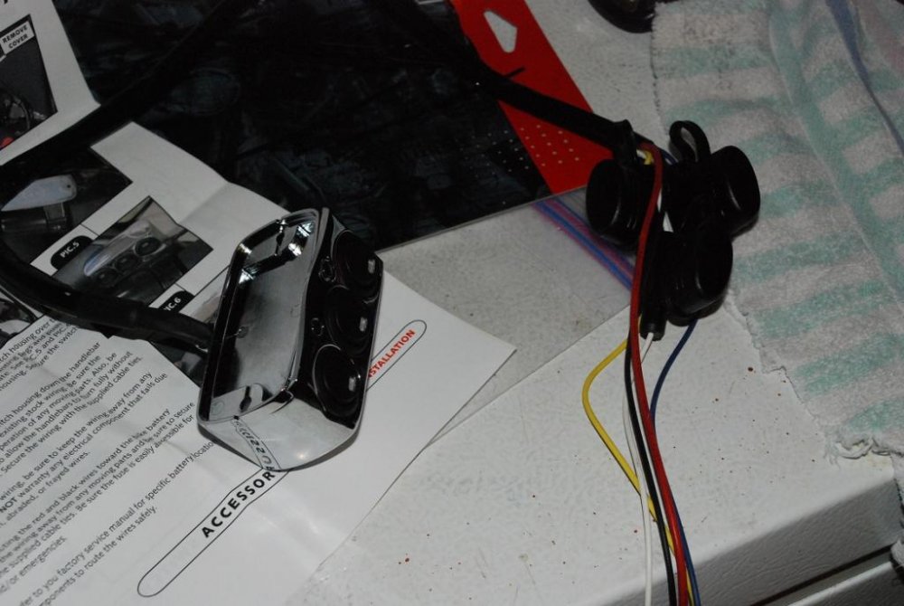
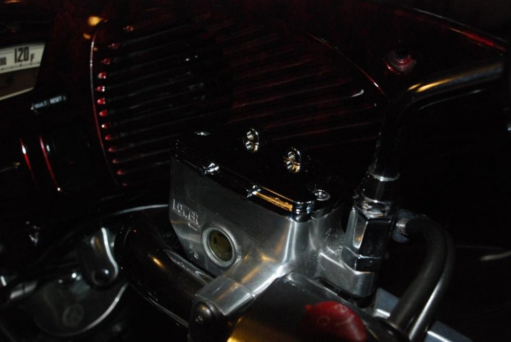
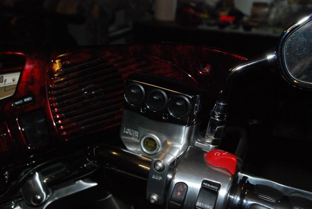
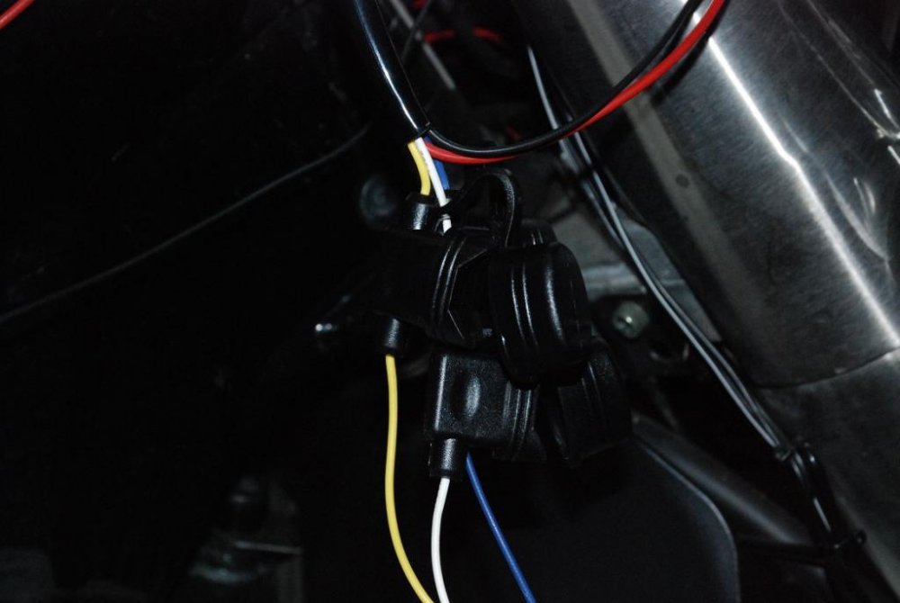
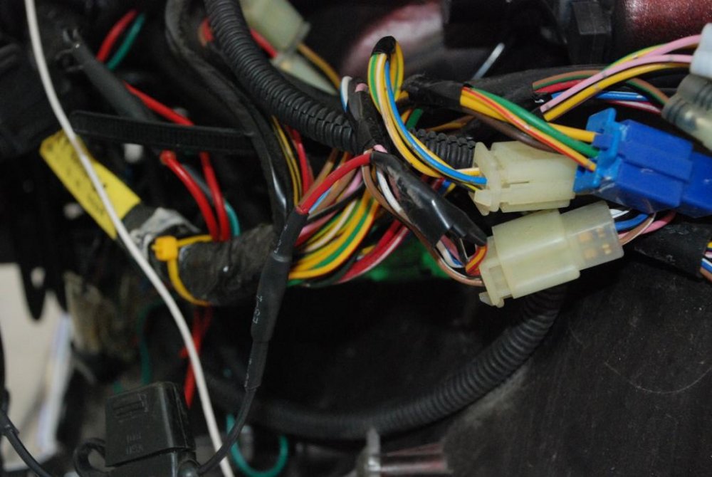
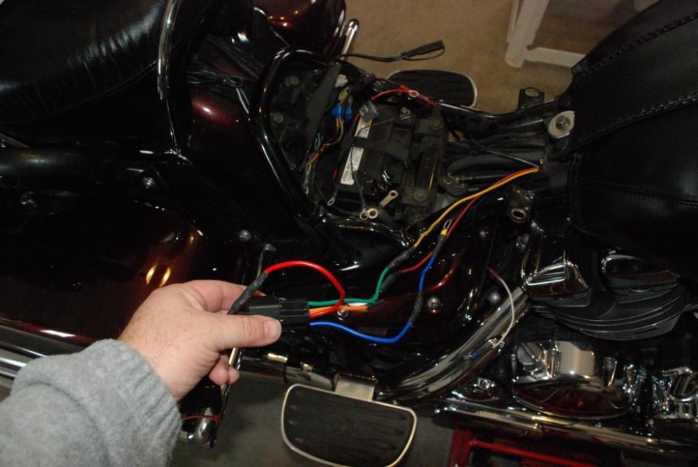
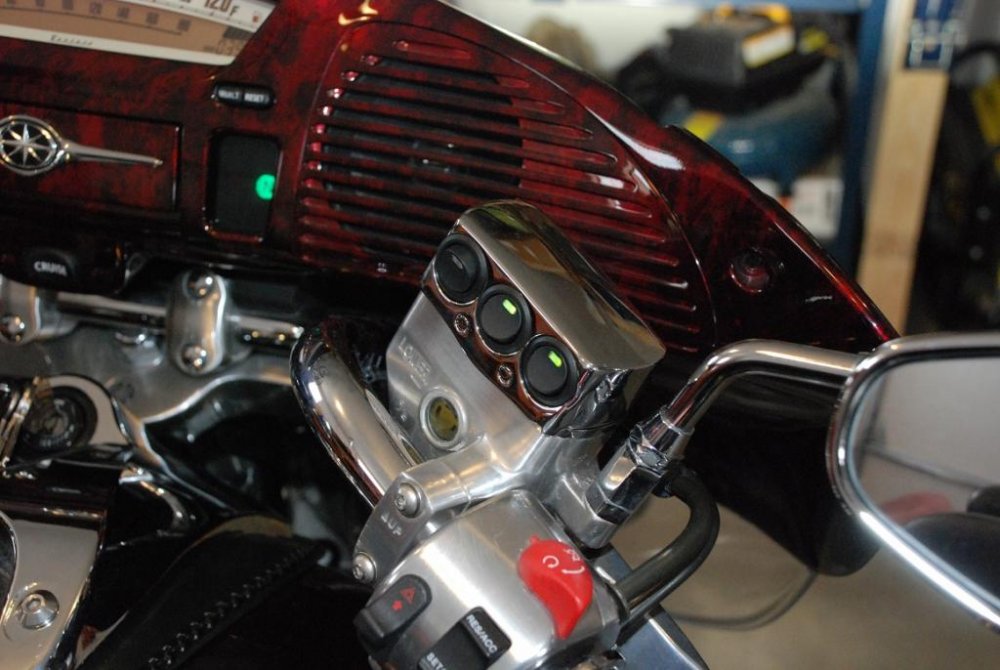
Am on a roll this weekend so I installed my Kuryakyn 3 way switch. Here is how it went. I had already split the fairing to install the LED headlamp yesterday, but now I also removed the tank to be able to run wires properly. Pic 1 shows the tank off and I ran the wires under the right hand cover plate. Pic 2 shows the unit as it arrives, fully wired to the switch with all of the fuse holders. First step is to remove the original master cylinder cover and replace with the one that comes with the kit. (Pic 3) Then install the switch housing on top of the new master cylinder (Pic 4). There are two screws that need to be put on from the back to lock it on. I then ran the wire harness along the handlebars aiming to get them into the fairing. That proved to be problematic as the fuse holders are placed too close to the unit and they are too big to squeeze though where the handlebars and fairing intersect. (Pic 5). So I cut them off and spliced the wires so they would be skinnier and then they passed through no problem. I know that if a fuse goes I will now have to split the fairing as that is where I relocated them, but I did not want a bunch off fuse holders hanging from the handlebars. Then you need to run the power and ground leads back to the battery. I also ran a lead from the original headlight ignition switched point (Pic 6) for the passing lamps from front to back. This will be my trigger wire for the relay. In the fairing, I then removed the original cheap yam switch for the passing lamps and connected the lamps to the new switch housing. Did the same for a second set of LED's that I run from the front fender. Both are now individually switched and fused and not tied to the headlamp for power. I then proceeded to the back and installed a relay between the battery and the switch. (Pic 7) A very special thank to Bongobobny who very patiently took the time to respond to my relay questions a while back. Other helped out also, but he really stepped up. Tested the switch (Pic 8) and then buttoned everything up with heat shrink tubes and secured all wires properly. Relay fits behind the battery. I have one switch that is not used yet. That circuit is still live so I simply removed the fuse for now in that one. Hope this helps others who may be looking at this install....
-
Are you sure about that for the 2nd gen? Yam says oil in fork is a non maintenance item:confused24:
-
2nd gen has oil filter in front below radiator and it is a spin off. Drain plug is just below it. Remember not to overfill above middle of sight glass, otherwise you will get blowby draining from the overflow tubes next to the kickstand.
-

CREE LED H4 Headlight Installation
Bert2006 replied to Bert2006's topic in Royal Star Venture Tech Talk ('99 - '13)
Thats a good point. I re-read the instructions and they recommend not using the rubber boot with these for the reason you state. Will be removing it tomorrow. Dont think water gets in there anyway. Thanks for pointing out. -
BITE ME.....:bang head::snow2:
-

CREE LED H4 Headlight Installation
Bert2006 replied to Bert2006's topic in Royal Star Venture Tech Talk ('99 - '13)
Yes, it is a direct H4 replacement. I ordered from this site: http://canadiancruisercustomizing.ca/products/afterburner-led-headlight-direct-replacment-lamps They now offer the 2800lm units as well as the 1800lm ones, but the 2800lm use more power.32w on LB and 64w on HB, amp draw is still very low though. Looks like they are out of stock for the 1800lm ones. -
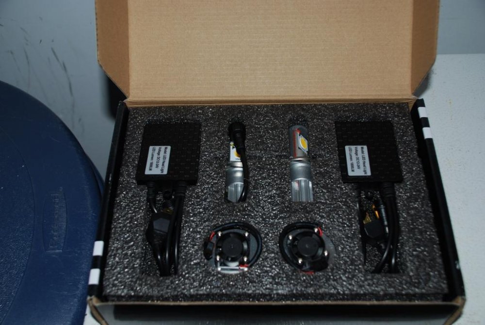
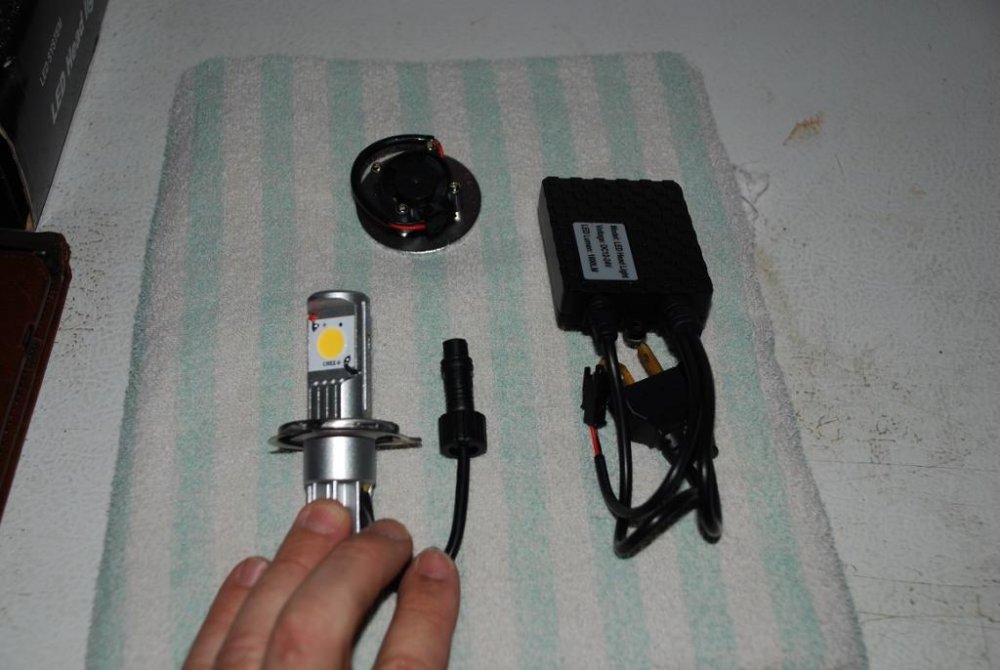
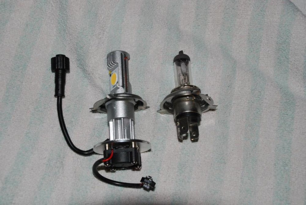
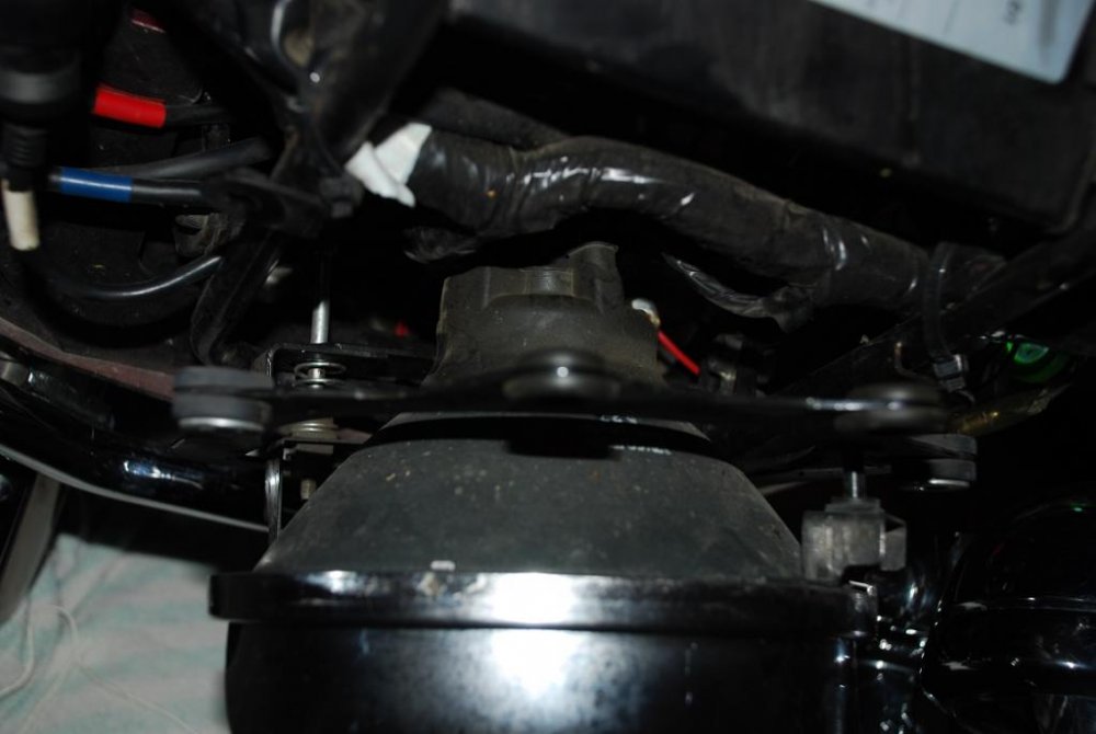
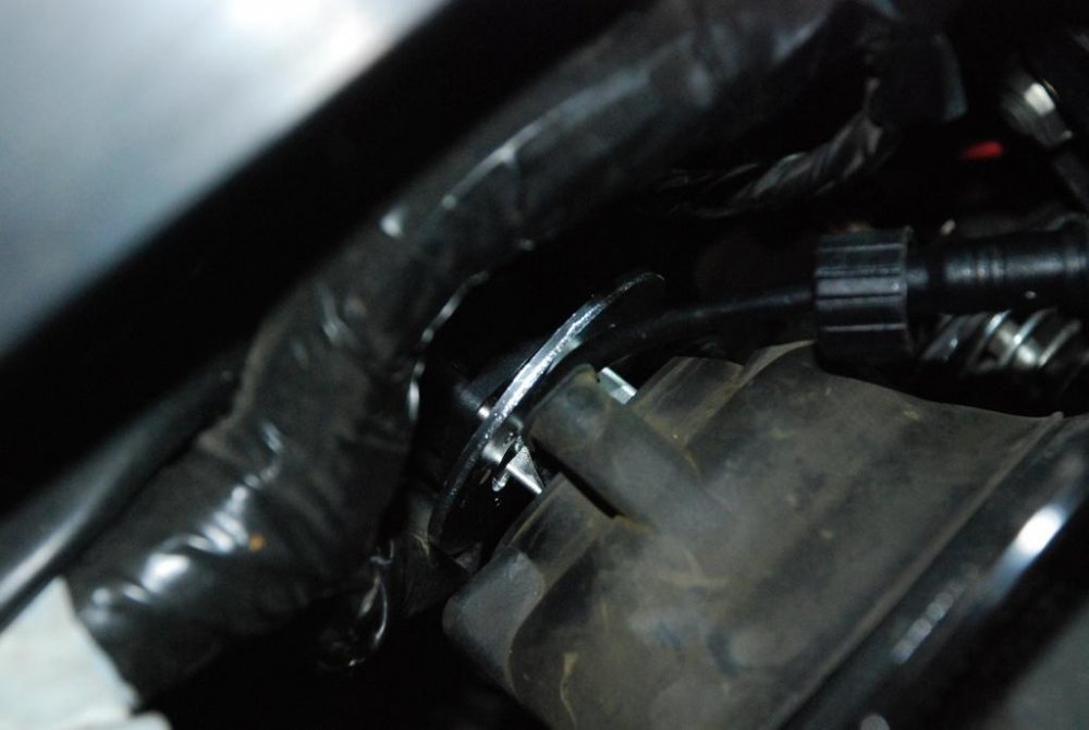
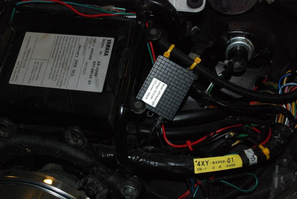
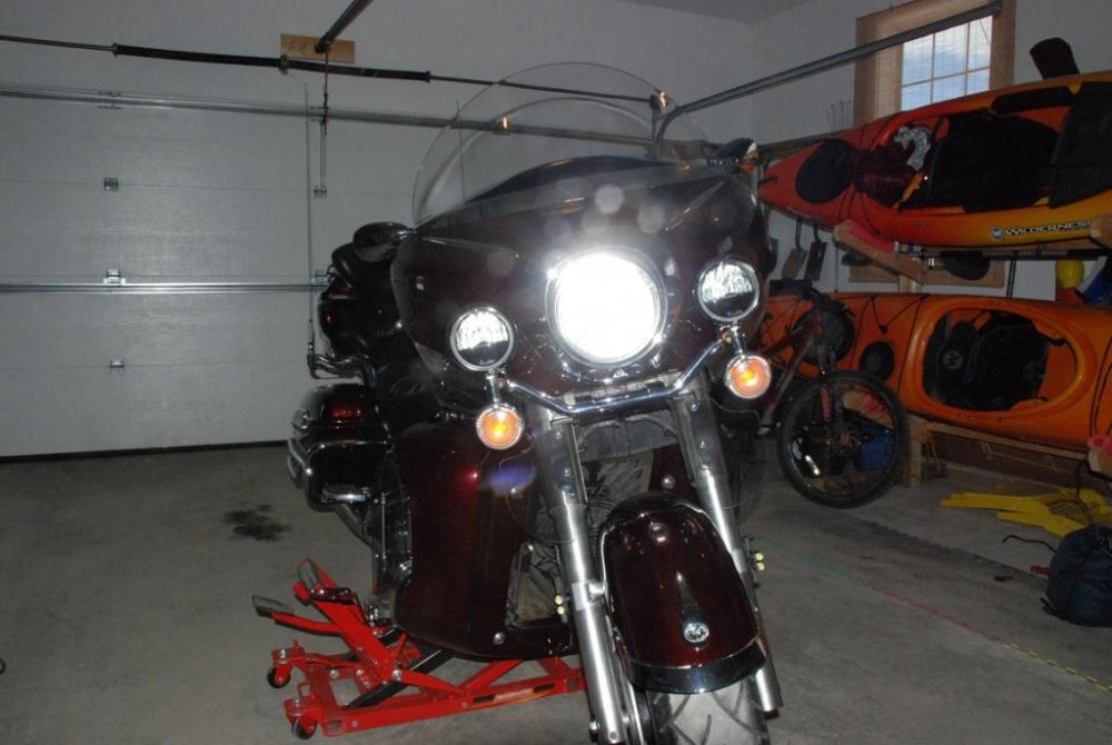
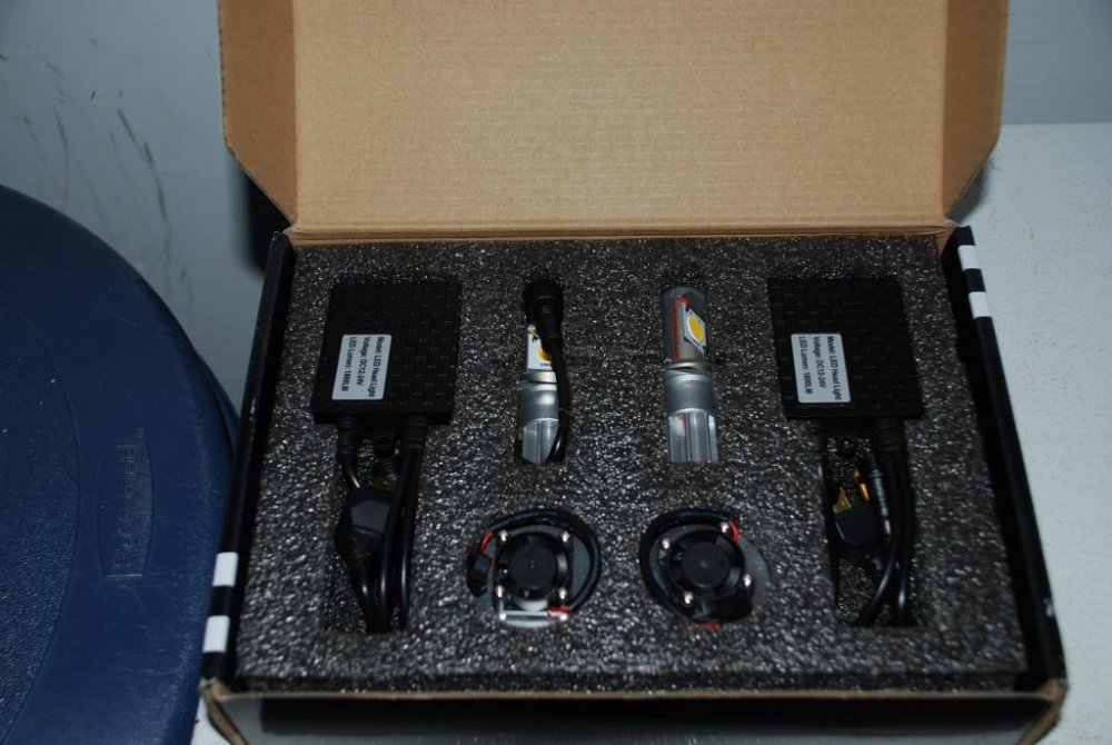
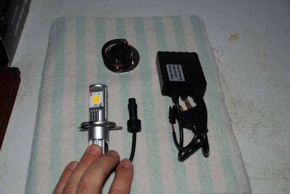
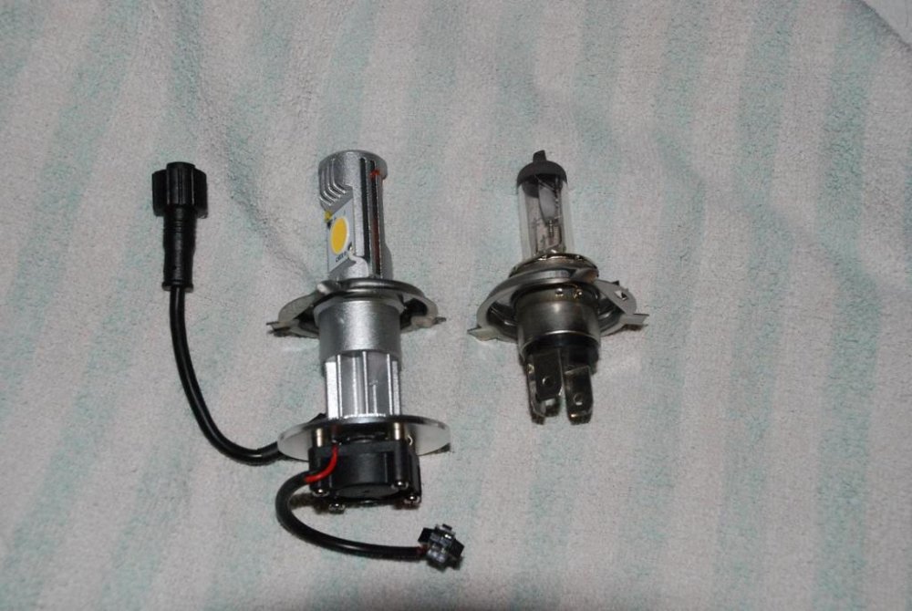
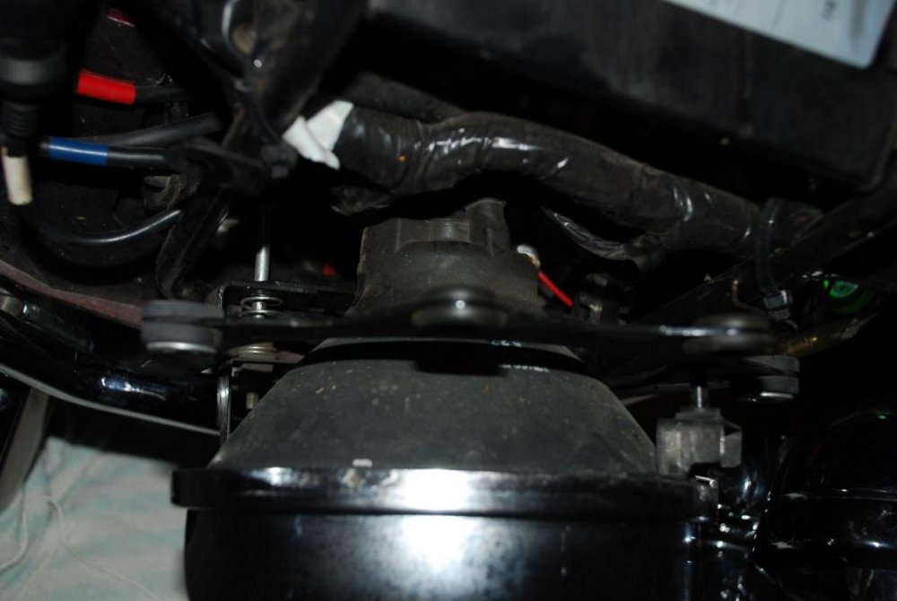
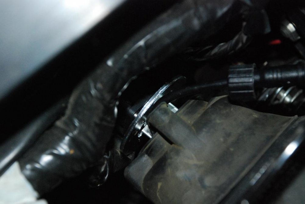
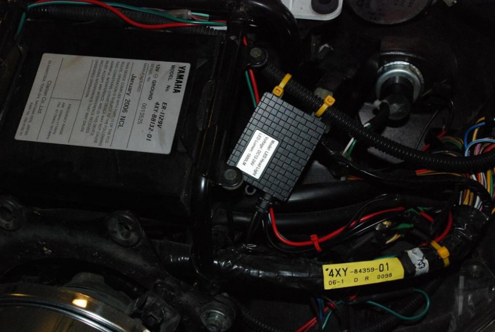
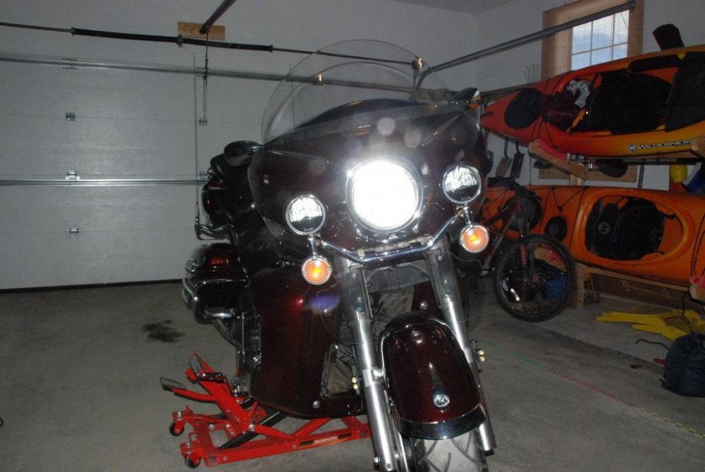
I EDITED THIS POST AS I HAD PART OF THE INSTRUCTIONS WRONG YESTERDAY. I was using the rubber protecting boot behind the headlamp bulb and you cannot use it as it will not allow the fan to cool the heat sink. Was able to install my CREE LED H4 Headlight bulb yesterday. It is an 1800lm bulb. Has hi/low beam. 6000k 20w for low beam and 40w with high beam on. Had to split the fairing to get to the bulb and also install the other pieces that came with the bulb. Going with the sequence of the pics below: Pic 1 shows you what comes in the box. I bought a double set. This way I have a spare available. Pic 2 shows the individual components, you get the H4 bulb, a fan and what looks like a ballast or driver. Pic 3 shows the difference in size between a reg H4 and the CREE H4. Pic 4 shows that I had to remove the 2 top bolts from the headlight housing so I could tilt it forward to get some space to work with. After disconnecting the original bulb, I removed the rubber cover (do not re-use), opened the retaining clip and then removed the bulb from the housing. To attach the LED to the housing you need to install the bulb in the housing like a normal bulb and replace the retaining clip. Pic 5 shows the lamp in place with the fan attached. To attach the fan unit to the back of the bulb, simply screw it on the end of the bulb housing. Use thread locker (not the permanent stuff) so it does not vibrate free. Next you need to figure out where the driver will be installed. I simply tie-wrapped it to a wire loom and then made my connections. There are three to make. a- connect fan to driver. b - connect bulb to driver. c- connect driver to stock headlamp connector from the bike. Pic 6 shows where the driver is sitting. Pic 7 show the led headlight on with (also) new led driving lamps. Took about 40 minutes to install. It looks like the low beam is very bright but there does not seem to be much of a difference with the high beam on, but that was just with an initial test in daylight in my garage. I will keep you posted on how it performs. Detail to remember are making sure that nothing rubs against the fan that would stop it from spinning and use thread locker so it does not vibrate free. Will keep the original bulb and rubber boot with me in case I have issues on the road as it would be simple to revert back to original if needed. Also, they now make a 2800lm version of this unit Hope this is useful.
-
Ok , got a chance to repair the wire today. It is one of the wires that feed power to the passing lamps. When you pull the passing lamps away to split the fairing it is pulled taunt, but when you replace the lamps it seems to get loose and then it is possible for it to get pinched. Need to check it after lamps are in place to make sure it is tucked out of harms way. Used liquid tape as suggested. Hope this helps....one more thing to watch for.
-

Front Tire Options - again!
Bert2006 replied to Bert2006's topic in Royal Star Venture Tech Talk ('99 - '13)
I will be ordering them today. Found them online for about $360 for the set including taxes and shipping. Will call dealer to see what his price would be. THANK YOU TO ALL WHO PROVIDED ADVICE IN THIS AND MY PREVIOUS THREAD, you where few but all positive and helpful. -
Welcome aboard. BEST RSV SITE ON THE INTERNET. I joined about this time last year and visit multiple times daily. Good source of advice:canada:
-

Front Tire Options - again!
Bert2006 replied to Bert2006's topic in Royal Star Venture Tech Talk ('99 - '13)
Bump- Dragonslayer is using all the bandwith today:confused24: -
I will be relocating it soon to the Kuryakin 3 switch pod that goes on top of the master cylinder. http://t2.gstatic.com/images?q=tbn:ANd9GcQf2o1W_TyBban2wcsvf8KZRJWTTOSHRgTOOmryRZCNjqnig5Mu6vR0NUAhttp://t2.gstatic.com/images?q=tbn:ANd9GcQZ5-8wYSVpR8ruoRH2u3lnkds4dbXv0_3dOIjQp_O5EG-3YnwKPWRCjA Will use one switch for the driving lamps, one for a set of visibility lights on my front fender and will have a spare for future use. Switch will be running direct from battery through a relay. Fused at 30 amps from battery, then each switch has a 10 amp fuse. Will be tackling this project soon and will be posting pics.
-

going to look at an 87 Venture Royale
Bert2006 replied to suds's topic in Venture and Venture Royale Tech Talk ('83 - '93)
See these threads for what to look for: http://www.venturerider.org/forum/showthread.php?t=1066 http://www.venturerider.org/forum/showthread.php?t=65738 -
Check this out: http://www.venturerider.org/forum/showthread.php?t=84450
-
Carefull now......:group cheers:
-
Hi folks, I am starting a new thread to see if there is any newer info (experiences) as most of the past threads on this topic date back a few years. In my last thread, I was seeking advice on replacement tires and I have narrowed it down to the Michelin Commander II's. In order to have a matched set of Commanders, I will need in the following sizes (Bias Ply): front - non stock (130/90-16) - it is not available in stock (150/80-16) size. back - stock (150/90-15) In the past threads some have mentionned having gone to the smaller size in the front and finding the handling to be too light and as a result have moved back to stock. Now that the Commander II has been out for more than a couple of years, I would be interested in finding out if others are using the above tire and size's and what your experience has been in using them. Also found this tire size comparator site that shows a graphic representation and comparison of different sizes: http://www.tacomaworld.com/forum/tirecalc.php Again, thanks in advance for your help! :bowdown: while others
-
Ok made my decision and I am going with the Michelin Commander II. I was leaning towards the E3s at first, but they do not offer the multi-compound in our sizes. They also seem to have some cupping issues. The Commanders are at the same price and are getting more consistent good reviews on durability and ride quality. Did give up on the WWW though, but value ride quality and durability more. Thanks to all who posted responses as it did help me make the call. Now lets have a collective talk with the man upstairs so that this winter can finally end.
-
Why not have window of time like a. week?:confused24:1 For this year on that date I will be in Europe but that is ok as every ride I take I usually think about someone - thats my therapy.
-
Great thanks, I will have another look.
-
Well, looks like I will be stuck with 404's for a while. In the standard sizes of 150/80-16 for front and 150/90-15 for rear I have found the following available: Dunlop 404 - available for front and rear in BW and WWW. Wear issues in the rear. Dunlop E3's - available in BW for the front, but nothing for the rear. Michelin Comander II - available for rear only and no WWW. Seem to have best record. Metzeler 880 - available for front in BW and WWW, but only in BW for rear. Tire chunking issues in rear. Avon Venom - available in BW for front and back, but too much talk about sidewall cracking Avon Cobra - available only for the front in BW, again sidewall cracking So from looking at a number of reviews in the past day's: - I have written off the Avon altogether because of the cracking issue. - Also would not use Metzeler in the rear as a result of the chunking issue. Here are my options: If I want to stick to WWW in a matched set, I am left with the Dunlop 404. Would still have the wear issue in the rear. If I forgo the match set and keep WWW, I could put a Metzeler in from and a 404 out back. Would still have a wear issue in the rear. In BW to get a matched set, I am left with the Dunlop 404. If I forgo the matched set, I could go with Metzeler or 404 or E3 in the front and Michelin in the rear. I would have preferred to go with a matched set and the Michelin's front and rear as they seem to get the best reviews or all, even if it meant not having WWW. Any thoughts:confused24::confused24: EDIT: Ok thanks to ACE50 and RedRider I was able to figure out some alternate sizes that would fit as follows: Rear: MV85H-15 Front: 130/90-16 and MT90B16 I will take another look at my options but I am now leaning heavily on the E3's or the Commanders.
-
I need to replace my front tire and am currently looking at options for my 2006 RSV. I currently have a Metzeler ME 880 in front and a Dunlop 404 in the rear. These are the tires it came with when I bought it last summer. The back one only has 5000 miles on it and still looks brand new. I usually run 36psi up front and 40psi in the rear. The front one will need to be replaced in the next month. I was looking at moving to the Elite3's but I cannot find them in the stock sizes for the RSV (150/80-16 front, 150/90-15 rear), nor can I find them with wide white walls. With the Metzeler, the only thing I dont like is that is seems to catch grooves and once in a while that transfers into a front wiggle. So any opinion on the Metzelers or where I could find Elite3's with wide whitewalls that would fit? Thanks ahead of time to those who respond.


