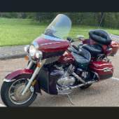
Paul Martin Posted March 12, 2025 #1 Posted March 12, 2025 (edited) I bought my 2001 RSV with 71K Miles on it. And it had a pogo-stick rear shock. I thought I would share my adventure of renovating the rear shock on the forum. I don't see any way that this shock can be disassembled any more than what is required to replace the O ring, and Yamaha says the shock is not rebuildable. But here's the deal. There is an O ring seal on the shaft just above the bottom clevis pin shock mount that will wear out and the shock fluid will leak out. When enough fluid leaks out, your rear suspension acts like a pogo stick. Running max air pressure may help a bit, but to fix it, that O ring needs to be replaced, and shock fluid replenished, which will often restore the shock to like new performance. It fixed mine! Credit to long time member @dfitzbiz (Dave) for the detailed instructions on how to replace the O ring. I PM'd him and he quickly sent the instructions and a pic of the tool he created to accomplish the O ring replacement. I guess he has a reason for not posting those detailed instructions in an article on the forum, so I will follow his lead and not post his instructions here. I have searched and read the "RSV Repaired Rear Shock 2000 Mile Update" post from top to bottom and searched the forum site but I don't see the detailed instructions that Dave sent to me posted anywhere on this site. So I am posting pics of my shock renovation journey, along with descriptions and comments. I gotta say, after putting in the new O ring and replenishing the shock fluid, the rear shock feels like new. Dave fashioned his shock expansion tool from what looks like 1" square bar stock. I did not have ready access to this material, so I ended up using what I had on hand to build a variation of Dave's tool. As you look thru the pictures, check for descriptions and comments below the pics. Here's the O ring spec you'll need. I ordered a pack of like 50 from WalMart for about $10. Amazon, eBay etc. should have it - search for: Buna N size 218 O ring Shock Before Removal Harbor Freight Mini Moving Dolly Under Rear Wheel Harbor Freight Mini Moving Dolly Mini Dolly under rear wheel allows bike to be moved on the rolling jack after shock is removed. Removing the air filler hose from the bike. Removing the air filler. Removing the air filler. Removing the air filler. AIS is in the way - gotta come outta there. AIS coming out. Ratchet in place on top shock bolt. I think it's a 17mm. Ratchet in place on top shock bolt. Top Bolt ready to pull out. Loosening the bottom bolt. Bottom bolt ready to come out. Lowering and removing the shock. Shock removed, AIS hoses plugged and capped. Used rubber plugs for the bigger hoses (see red circle). Poor dirty old shock. Nice purty cleaned up old shock. What's behind the curtain? Removing the boot. Removing the boot. Boot removed. Boot removed. Hang the shock upside down and remove the air valve to allow shock fluid to drain. Draining the shock fluid. Draining the shock fluid. After about a day, less than 50ml drained out from the shock. After two more days, still the same. I waited that long only because I couldn't get back to this project for a couple of days, and figured it would be good to make sure it all drained out. So that's why my shock was pogo-ing. 50ml is not enough to provide damping. Maxing your air pressure to 57psi might help a bit but won't totally stop the pogo-ing. Now, if your shock won't keep air, I believe that is a separate problem. My shock would hold air pressure even tho the O ring was leaky. So my guess is there's another chamber or rubber balloon that handles the air pressure. Well, in retrospect, the above can't be right. The air goes in the same hole that you pour the shock oil into so the damping mechanism and air chamber are connected. Comments and experienced observations are welcome here! Less than 50ml of old fluid came out of my shock. Dave recommends refilling a shock with 125ml. Fabricating the expansion tool. So this piece of steel channel stock was cut from a 6 foot length I found laying in the middle of a street about 15 - 20 years ago. You never know when you might need a chunk of channel stock, right? Shock bolt will go thru this hole. Pusher bolts will go thru the two smaller holes. Lube the new O ring. Carefully slip the new O ring over the clevis and down onto the collar at the base of the shock. Carefully slip the new O ring over the clevis and down onto the collar at the base of the shock. Carefully slip the new O ring over the clevis and down onto the collar at the base of the shock. I made this pressure plate from plywood. It's not really sturdy enough for doing multiple shocks, but it worked fine for this one shock. This spreads the pressure from the pusher bolts out so as not to deform/bend the bottom of the shock housing when the pusher bolts are tightened. Expansion tool mounted and ready to pull the shaft up to expose the old O ring. Expansion tool mounted and ready to pull the shaft up to expose the old O ring. Tightening the nuts on the pusher bolts. The nuts push the tool and shaft upwards while the bolts push down against the shock body. O ring starting to show in the gap as the shock is expanded. O ring starting to show in the gap as the shock is expanded. Slip a small screwdriver under the old O ring and pull it out from the groove. Snip the old O ring and pull it out of the shock. Old O ring is clipped and ready to be pulled out. Old O ring. Clean and lube the groove that the O ring fits into. Clean and lube the groove that the O ring fits into. Use a small screwdriver to carefully coax the new O ring up off the collar and into the groove. Use a small screwdriver to carefully coax the new O ring up off the collar and into the groove. Use a small screwdriver to carefully coax the new O ring up off the collar and into the groove. New O ring in place. Clean it up as good as you can. New O ring is in place. Make sure it's still adequately lubed. Slowly back down the nuts on the pusher bolts to allow the shaft to retract back into the shock body. Remove the air filler hose from the shock body, and lay the shock at a slight angle with the filler tube up. I used a cheap meat injector from WalMart to refill the shock with 125ml of Yamalube 10 Fork & Shock Oil. I used a cheap meat injector from WalMart to refill the shock with 125ml of Yamalube 10 Fork & Shock Oil. I used a cheap meat injector from WalMart to refill the shock with 125ml of Yamalube 10 Fork & Shock Oil. I used a cheap meat injector from WalMart to refill the shock with 125ml of Yamalube 10 Fork & Shock Oil. I trickled the fluid in a few drops at a time to allow it to ingest into the shock body and avoid it bubbling back out. That way I'm sure all 125ml goes into the shock and I'm not guessing how much bubbled out. Connect the air filler hose to the shock body and pressurize the shock to about 40psi to test for leaks. Reinstall the shock into the bike. Reattach the air filler hose to the bike. Shock reinstalled. Rear AIS deleted. Put the side panels and seat back on the bike and ENJOY THE RIDE! Edited May 26, 2025 by Paul Martin Added descriptions & comments. Clarified description of pusher tool/bolts & nuts. Fixed comment formatting. Added a couple of pics of plugged AIS hoses. Added O Ring spec. 2
N3FOL Posted March 12, 2025 #2 Posted March 12, 2025 Thanks for posting your experience including pics. Very informative indeed. 1
Chaharly Posted March 12, 2025 #3 Posted March 12, 2025 Very cool, and a creative fix ta boot! Here's to 100k more worry free miles on that shock! Enjoy! 2
RDawson Posted March 13, 2025 #4 Posted March 13, 2025 I talked to Dave last summer at the Asheville rally, he’s shipped his repaired shocks all over the globe. I have the instructions bookmarked but they’re on here somewhere, not sure where. He did a demonstration at one of Freebird’s MD weekends several years ago, great guy to deal with also if you want him to fix it. 2
Mark George Posted May 25, 2025 #6 Posted May 25, 2025 Can you share with us the size O Ring and where it can be obtained.
Paul Martin Posted May 26, 2025 Author #7 Posted May 26, 2025 Buna N size 218 O ring I ordered a pack of like 50 for about $10 from WalMart. Should be available from Amazon/eBay.
InfinitySurf Posted June 12, 2025 #9 Posted June 12, 2025 Very nice write-up! I sent my leaking shock to Dave in 2021 when I bought my 2012 RSV and its been great ever since. Been in the back of my mind that at some point I may have to replace the o-ring in the future since I plan to keep my bike long-term, so appreciate the detailed write up being available here. 1
JD 520 Posted June 29, 2025 #10 Posted June 29, 2025 Thanks for the info. Thinking of selling my 2012 rsv with 15,000 mi to Yamaha of Louisville KY. They want to knock down an already low ball offer because of wetness on rear shock. I'll now can fix it myself. AD Shaffer

Recommended Posts
Create an account or sign in to comment
You need to be a member in order to leave a comment
Create an account
Sign up for a new account in our community. It's easy!
Register a new accountSign in
Already have an account? Sign in here.
Sign In Now